
----- Critically Important -----
- Flash graphics viewing/use alternatives:
-
Flash support by most modern browsers has been dropped but that's not the end of the line for Flash.There is no practical alternative to Flash for the interactive demos/applets/graphics on this site.. Especially when there are alternatives, some simple, some good, some...
- Ruffle is chosen by most because they can't imagine using anything but their preferred browser. It works. It's OK but not great. The Flash graphics won't look as they're supposed to but it, generally, works.
- The #1 preferred (my me) way to view the site and the Flash graphics is with the Chromium Portable browser and the installation of the older (no time-out) Flash Player files. This was incredibly simple when people knew computers but not today when people only know how to work with their phones.
- The Flash Browser is a good option but it's so stripped down that it makes it somewhat difficult to use.
- The Maxthon browsers are an option. The v4.95 is the easiest (install and use). V5.3.8 and 6.1.0 require (very) slightly more effort (very).
- All of these browsers are available from my Flash Information page.
- The Chromium and Maxthon browsers on the page above are 'portable' browsers. They are not installed into your system. They are simply made available for use on your computer. They can be carried around on a Flash drive and used on any computer.
----- Critically Important -----
Basic Car Amplifier Repair Tutorial
(now available as a downloadable file)
 Many people need help repairing their amplifiers but are afraid to ask for help because they don't want to sound like an idiot (asking stupid questions, etc...). The information on this page will help prevent asking questions that may be deemed as stupid. 'Stupid' questions are generally those asked by someone without enough knowledge about the subject to ask meaningful/useful questions. If you take the time to read this page in a manner that will allow you to absorb most (or all) of the information here (expect to spend at least one full hour reading and re-reading -- maybe a bit more if you're struggling to understand it), you will learn the proper terminology and the basic operation of an amplifier. In most instances, most of your questions will be answered here and you will only need a bit of clarification for your specific amplifier.
To help the page load more quickly and to save bandwidth, many of the photos will be loaded from links. When you're done viewing the photo, close the window. If you leave it open and return to this page, the next photo may load in the background window and it may appear as if the link isn't working. The green links are photos. Most of the other links are to web pages on this site. If you're serious about learning to do this type of work, you should follow the links and read the pages from top to bottom. There are too many people who claim to be serious about amplifier repair and fail to read EVERY linked page. Those with an honest desire to learn the material, not just reading to say that they have done so, will read and re-read the linked pages until they truly understand the material.
Many people need help repairing their amplifiers but are afraid to ask for help because they don't want to sound like an idiot (asking stupid questions, etc...). The information on this page will help prevent asking questions that may be deemed as stupid. 'Stupid' questions are generally those asked by someone without enough knowledge about the subject to ask meaningful/useful questions. If you take the time to read this page in a manner that will allow you to absorb most (or all) of the information here (expect to spend at least one full hour reading and re-reading -- maybe a bit more if you're struggling to understand it), you will learn the proper terminology and the basic operation of an amplifier. In most instances, most of your questions will be answered here and you will only need a bit of clarification for your specific amplifier.
To help the page load more quickly and to save bandwidth, many of the photos will be loaded from links. When you're done viewing the photo, close the window. If you leave it open and return to this page, the next photo may load in the background window and it may appear as if the link isn't working. The green links are photos. Most of the other links are to web pages on this site. If you're serious about learning to do this type of work, you should follow the links and read the pages from top to bottom. There are too many people who claim to be serious about amplifier repair and fail to read EVERY linked page. Those with an honest desire to learn the material, not just reading to say that they have done so, will read and re-read the linked pages until they truly understand the material.
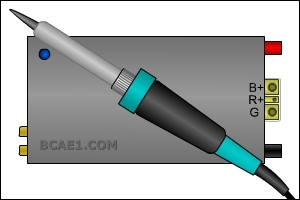
This page is here to help answer many of the questions that I get about basic amplifier repair. This is essentially a 'Cliffs-Notes' type page and isn't nearly as detailed as the tutorial I sell. However, it should answer many of the basic questions. Unless otherwise noted, this page will be dealing with class AB amplifiers (most full range amps are class AB or some variant, class A, class B). If you have a question about a repair, feel free to email me. Be Pro-active if you want to Learn to Repair Amplifiers: If you're interested in doing repair work and you have to constantly wait for someone to provide every minute detail, you probably won't make it in this business. For example, if someone states that the datasheet for an IRFZ44 provides specific information for that component and you ask the person helping you what a datasheet is, you are not well suited for this type of work. Someone well suited for this type of work would have immediately Googled 'datasheet' and 'IRFZ44' and would have immediately had the answer. This would save the time between the posts or emails from the person helping you with the repair (or whatever you're doing) and shows that you're thinking and willing to put forth a bit of effort. This tells me a lot about a person's willingness/drive to learn. Too many people are lazy and would prefer to wait on an answer because that lets them relax and gives an excuse for doing nothing. If you're the type of person that prefers waiting, you are not likely well suited for any job where you have to think (and this type of work requires you to constantly use logic to find various faults). This may sound harsh and may make you angry (some people are very easily angered) but I know what it takes to make it in the repair business and being lazy won't cut it. Basic Amplifier Layout: Most amplifiers have switching power supplies. Generally, the power supply will be on the end of the amplifier near the B+ and ground terminals. The audio section of the amplifier is generally on the other end of the amplifier (most commonly the end where the RCA jacks are located). The power supply produces the various voltages required for the audio section. If the power supply is blown, there will be no audio (in most cases). 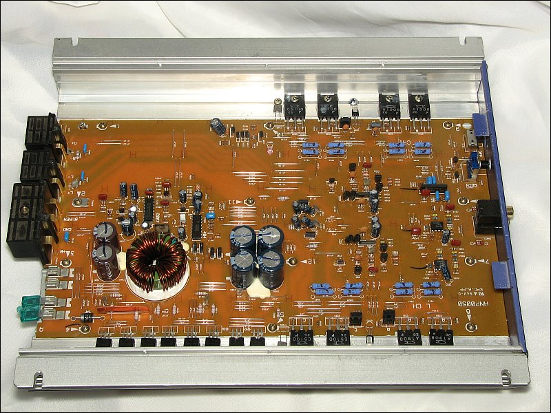
If you think you'd like to be an electronics technician, you'll have to decide whether you want to understand the circuits, troubleshoot the problem and replace only the components (or group of components) that are necessary to repair the amplifier. Most have a low opinion of mechanics that are 'parts changers'. Because they don't understand the operation of the various components in the vehicle well enough to troubleshoot properly, they make a guess as to what needs to be replaced and continue until they get lucky and find the defective part. This is time consuming and expensive. If you want to be a knowledgeable technician, you can learn on your own but that takes a lot of trial and error. The cost of the tutorial below is far less than the cost of the components that most rookie techs will destroy in their first few repairs. 
Updated January, 2025
Actually, it's updated virtually every day.
Click HERE to open this graphic in a new tab. Right-click to zoom. Left-click to drag. babin_perry@yahoo.com
Commonly Used Terms
Understand What Your Multimeter is Telling You
Common Symptoms
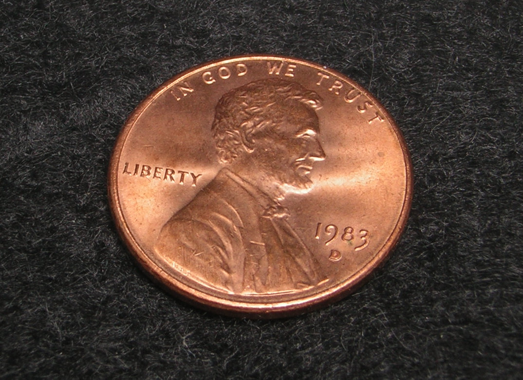
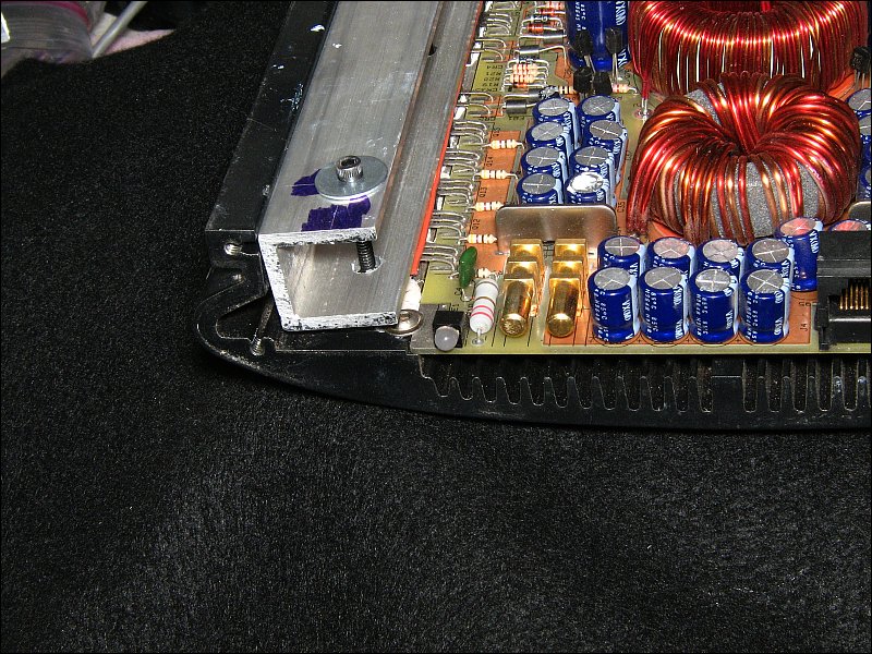
Amp Failure:There are many different ways that an amp can fail but the two most common failures are shorted output transistors and blown power supply transistors. The power supply FETs in this amp aren't blown. Many times (most of the time) power supply transistors are visibly damaged but that's not always true. If you clicked the links, you should have noticed that the power supply FETs were in a smaller case/package than the output transistors (look at the screw head for scale). In most instances for class A, class B or class AB amplifiers, the output transistors have to dissipate more heat than the power supply transistors and the larger case makes it easier to transfer the heat from the transistor to the heatsink because there is more surface area on the large transistor case. There are several types of protection circuits in amplifiers. The most common are over-current and thermal. The over-current protection is supposed to protect the output transistors. Sometimes it doesn't work well enough to prevent the failure of the output transistors but it will work well enough to shut the supply down before the power supply FETs are destroyed. If the amp remains in protect mode, goes into protect mode or blows the fuse as soon as the remote voltage is applied, shorted output transistors are almost certainly the cause. Important: All of the transistors clamped to the heatsink are 'power transistors'. 'Power transistors' are typically any transistor capable of dissipating 10 or more watts of power. To dissipate the heat generated when dissipating that much power, they are typically clamped to a heatsink. The FETs that drive the power transformers should be referred to as 'power supply transistors' or 'power supply FETs'. The transistors that are used to drive the rail voltage to the speakers should be referred to as 'output transistors'. If the transistors are FETs, you can refer to them as 'output FETs'. When bipolar transistors are used as output transistors, they're typically referred to as simply 'output transistors', not 'output bipolars'. If the fuse protecting the amp is too large, if the protection circuit doesn't respond quickly enough or if the power supply is poorly designed, the power supply transistors may fail. If you see a lot of black soot on the power supply transistors (near the power transformer), the power supply transistors have failed. Soot on the board doesn't necessarily mean the transistors have failed. Sometimes, technicians don't clean up the mess from a previous failure. Transistor Failure/Checking Transistors: In general, when a transistor fails, it will either short (common for output AND power supply transistors) or open (common for power supply transistors). Transistors act like valves. They control the current flowing through a circuit. A shorted transistor acts like a valve that's stuck open (passing too much current). In the case of an output transistor, the shorted transistors tries to deliver the full rail voltage to the speaker output terminal. If you've ever seen a damaged amp that pushed or pulled the speaker cone to its limits when the amp powered up (common on some Rockford amplifiers), that was almost certainly due to a shorted output transistor. When checking transistors, you most commonly look for shorted connections inside the transistor. You do this by using a multimeter to look for low resistance connections between the transistor's terminals. Note:
I used the terms short and open on the previous paragraph. A short (short circuit) is a path through which current flows that should not be there. An open (open circuit) is a break in the circuit.
Right-click to zoom in. This page is a VERY basic introduction into car audio amplifier repair. If you're interested in learning more about troubleshooting, the commonly used components in car amplifiers and the way they work, you may be interested in the full version of the repair tutorial. The full version also contains many examples of common problems with many of the most common amplifiers. This includes tips for common problems that may not be apparent when replacing blown components which can result in premature failure of the amplifier. If you're interested in learning more, click HERE. Parallel Components
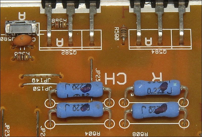
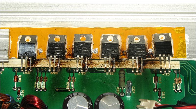
In most amplifiers, you'll find groups of parallel components. The components are used in groups because a single component can't handle the stress. When in parallel groups, the components MUST have virtually identical characteristics. If one or more are just slightly different, the load will not be shared equally and it can cause the amp to fail prematurely. When one component in a parallel group fails, all in the group MUST be replaced for optimum reliability. Even if the replacement part has the identical part number, it will not be exactly the same as the original parts and won't share the load properly. The date or production code is a good way to identify parts that are very similar. Parts with the same date code will have identical markings printed/etched on their face. If there is any difference in the markings, they may not be well matched. If the parts have the same date code, they are going to be closely matched. Generally, when you order parts, you get the same date code but that's not always the case. If you buy 6 parts and the distributor has them prepackaged in packs of 1s, 5s, 10s, you will get one pack of 5 and one single pack. These are unlikely to have the same date code. If you are not ordering a full stick of parts (50pcs/stick for TO-220 parts), order more than you need so you can be relatively sure you will get enough matched parts.
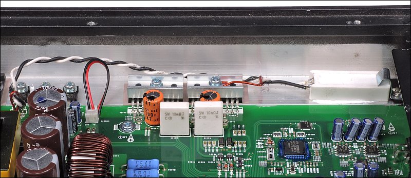
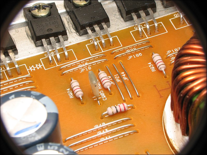
The following image shows the parallel components for an audio amplifier. The configuration will vary from amp to amp but the basic layout of the parallel components will be similar to what you see here. For switching power supply components, there are no emitter resistors. This makes the matching of the components that much more critical.
Datasheets
Datasheets are documents that tell you virtually everything about a particular component (including pin configuration, the pin numbering scheme and the names of the individual terminals -- particularly important for transistors). For a single transistor, they can be 10+ pages long. For ICs (Integrated Circuits -- chips), they can be 20+ pages long. Datasheets can be used to find the specifications like current capacity and maximum operating voltage. This is handy when you need to substitute a part that's no longer available. If you need a datasheet, use Google and search for 'datasheet' and enter the part number of the component. If you use Octopart, you don't need to enter the term 'datasheet'. A link to the datasheet will be provided when the results for the search are returned. If you use Mouser or Digi-Key for parts, when you look up a part, a link will be provided for the datasheet on the information page for the part.
Parts Substitution
In general, it's best if you use replacement parts that are the same exact part number as the original. In some cases, it's OK to make a substitution if the replacement has better specifications than the originals. Until you know an amplifier very well, use the original parts. In class D amplifiers, you should not make any substitutions. In some cases, the new replacements will vary enough from the originals that the same part number component will not work properly.
Surface Mount Components
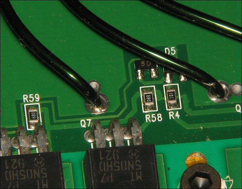
Surface mount components make a repair slightly more difficult. They are typically smaller and the pads can be damaged easily if you're not careful. Using good equipment and good technique, you will be able to replace them easily. In THIS photo, you can see several surface mount resistors and a surface mount semiconductor (a diode). These commonly burn when the power supply fails. To remove them, you apply new solder to both sides, heat one end for 2-3 seconds and then move the iron to the other side. When the solder melts, the resistor will slide off of the pads (if it's done quickly enough that the other side hasn't had time to cool).
You read the value off of the surface mount resistors just as you would for resistors that use color codes (except you don't have to remember the colors). The resistors marked 680 are 68 ohms. The resistor marked 101 is 100 ohms. Refer to the Good Quality Equipment/Tools
For those who will do a lot of repairs, you will need a sturdy set of shelves. The following shelving unit is one that I built to for my shop. If you're interested on building it, you can find the 3D model and information for the software to view it on one of my OTHER sites. Go to page 10a in the directory of the site. 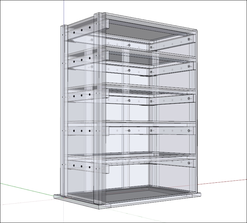 Back to Repair Information...
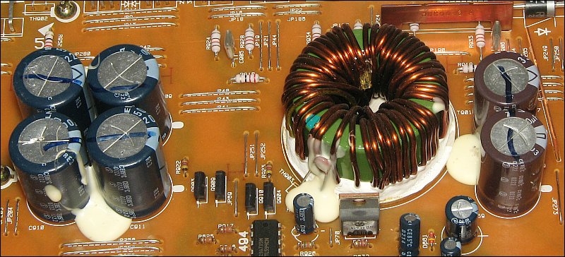
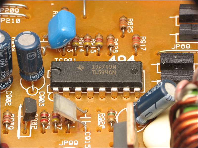
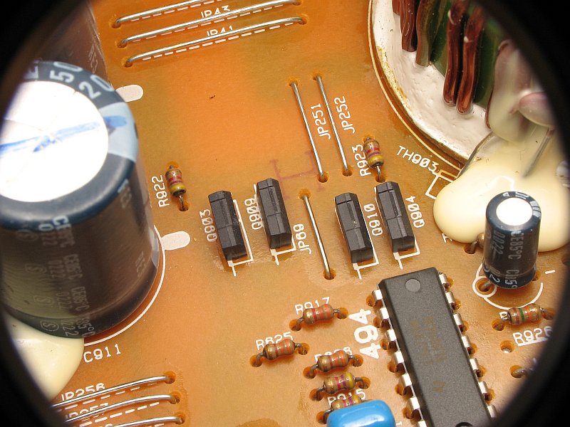
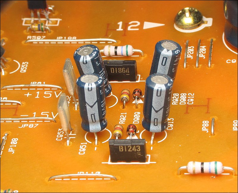
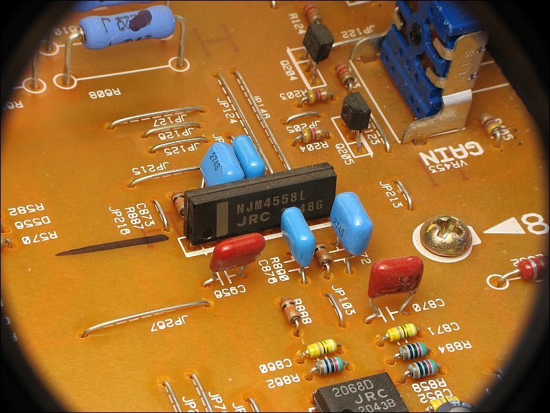
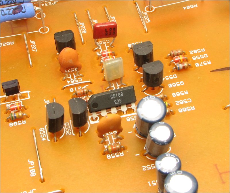
Gate Drive Signal:I previously mentioned power supply drive circuits. Here, I'll go into a bit more detail. The TL594 (or it's close relatives, the TL494 or the KA7500) produces the square wave drive signal. In some amplifiers, the power supply voltage is regulated. For regulated power supplies, the square wave output has a variable duty cycle. It modulates the pulse width to maintain the target rail voltage. This means the the 'on' time won't always be 100% (50% per output). For more information on PWM supplies, follow THIS link. For unregulated supplies, the pulse width is constant. For the TL594, the output is typically taken from pins 9 and 10 (MTX, Sony and a few other amps use pins 8 and 11 as the outputs). This is driven into driver transistors. In THIS photo, the drivers are the small rectangular components with the circuit board designations Q903, Q909, Q904 and Q910. They act as buffers and produce higher drive current than the TL595 can produce. The driver transistors drive the square wave signal into the gate resistors (the resistors connected to the gate terminal of the power supply FETs). In the photo, resistors R924, R928 and R934 are the gate resistors for 1 of the 2 banks of power supply FETs (3 FETs per bank in this amp). In most amplifiers, the value of the gate resistors is between 27 and 100 ohms. These are a bit higher at 120 ohms. It's common for the gate resistors to fail when the power supply transistors fail. As I mentioned before, the gate often shorts to the drain (terminals 1 and 2 of the FET -- look at the IRF1010EZ datasheet, page 9). When this happens, the drivers have to work against the internal short of the FET to try to pull the gate voltage down. It's essentially impossible because the terminals are fused-together internally and terminal 2 is essentially connected directly to the B+ terminal of the amp. If the drivers are tough, the gate resistors will fail. if the drivers can't handle the current (when trying to pull the gate voltage down), they will fail (unless the gate resistors fail first). Rectification and Filtering: The output of the power transformer is sent to two dual rectifiers. All of the positive pulses pass through one rectifier and to the positive rail capacitors. The other other rectifier passes all of the negative pulses to the negative rail capacitor. This rail voltage is the source of power for the outputs transistors in the audio section of the amplifier. When troubleshooting an amplifier, you must confirm that the power supply is producing both positive AND negative rail voltage. There are a few amps that don't have negative rail voltage. The class D amps based on the HIP4080 driver IC will only have positive rail voltage. Lower voltage (±15v) will be produced for the preamp section of the amp but the power amplifier section doesn't use a negative power supply. 'Chip amps' which operate off of the B+ voltage (like the internal amplifier of a head unit) do not have a switching power supply and will not produce a negative power supply voltage. Linear Voltage Regulators: In most amplifiers, the rail voltage is much too high for the op-amps. To lower the voltage, voltage regulators are used. There are many types of regulators. In this amplifier, Zener diodes are used to set the regulated voltage. Series-pass transistors (BJTs) are used to increase the output current capacity of the regulator. The regulators for this amp can be seen HERE. You must confirm that the pre-amp op-amps have both positive and negative supply voltage. You will find regulated voltage from ±10v to ±18v in amplifiers. ±15 is the most common voltage for the op-amps. Getting a Clean Input Signal: In most amplifiers, the input circuit is either an active noise cancelling circuit or the amplifier has an isolated secondary. You can find more information about these on THIS page. This amplifier uses an active noise cancelling circuit. Most budget amplifiers use an isolated secondary. The input op-amp is generally very near the RCA jacks like THIS. It takes 2 op-amps for each input. Each of the 8 pin op-amp packages in the photo contains 2 op-amps. Crossovers/Filters: Not all op-amps are in flat packages. THIS dual op-amp is in an SIP (Single In-line Pin) package (vs the DIP, Dual In-line Pin package). The op-amps in this package are being used in the filter (low pass crossover) circuit. The low pass/bypass switch on this amp selects between the crossover or the full range signal. Power Amplifier Section: After the switch, the signal is fed into the power amplifier section. In virtually all commercially available, solid state amplifiers, there is an error correction circuit. It greatly reduces the distortion at the output of the amplifier circuit. The 'brains' of this error correction circuit is the 'differential amplifier'. The input signal is fed into the input of the differential amplifier. A fraction of the output circuit is fed back into the other side of the differential amplifier. If there is any difference in the two inputs of the differential amplifier, the error will be corrected. In this amplifier, the two transistors of the differential amplifier are in one package. This insures that the transistors are closely matched and maintain the same temperature (which helps insure that they remain matched). Note:
For most of the transistors using the Japanese numbering system, you add a 2S prefix to the part number. The dual transistor above is a 2SC5168. For transistors manufactured by KEC, the prefix is KT instead of 2S.
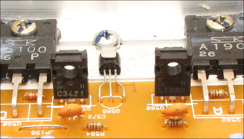
In most amplifiers, the differential amplifier is driven into a voltage amplifier. A differential amplifier can't swing its output fully from rail to rail but the voltage amplifier can (or at least get very close to the rails). The voltage amplifier drives the driver transistors and the driver transistors (2SC3421 and 2SA1358) drive the output transistors. The output transistors drive the speakers.
Sometimes, when the output transistors fail, they will cause the drivers to fail. If you're repairing an amplifier that has blown output transistors, you should check the driver transistors also.
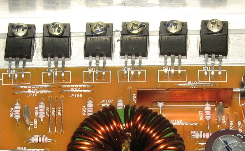
In the driver transistor photo, you can see a small transistor between the output transistors on the heatsink. This is a bias compensating transistor. Previously, I mentioned that the dual transistor package insured that the two transistors maintained the same temperature. If the transistors are not at the same temperature, their electrical characteristics will not match (even if they are otherwise identical). The same is true for the output transistors. If you set up an output section to where there is always a tiny current flowing through the transistors (class AB operation), this current will change as the temperature of the transistors changes. To compensate for the changes in the electrical characteristics of the output transistors, a bias compensation circuit is used. The small bias compensation transistor prevents the bias current from changing significantly. Without it, the output current would increase significantly as the temperature of the output transistors increased.
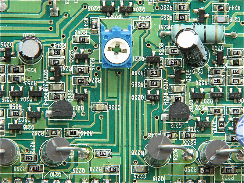
Many times, there is a bias adjustment potentiometer. It allows you to set the bias/idle current of the output transistors. If the bias is set too high, the outputs will run too hot and be more likely to fail. If set too low, the output could be distorted. There have been many instances where someone has gone into an amplifier and turned the bias pot up (thinking that they were increasing the power output of the amp). This caused the amp to fail. Unless a potentiometer is accessible from the outside of the amplifier, you should not turn it unless you know what it is. Having the bias current set too high is like having the idle setting on your car's engine set to 3000 RPMs instead of 750 RPMs.
Troubleshooting a Dead Amplifier
Previously, we looked a scenario where the amp would try to power up but would go into protect or blow a fuse. Troubleshooting a dead amplifier is different.
When an amplifier will not power up, you have to confirm that you have ~12v across the B+ and ground terminals. You also must check the fuses (all must be intact). If those check out, you need to open the amp and look for signs of damage. If there is no visible damage, you need to begin checking voltage on various points. Connect your black meter probe to the chassis ground terminal of the amplifier. Measure the voltage on the center leg of the power supply FETs. It should be at or near 12v. If that's as it should be, check the voltage on each pin of the TL594 (or whatever driver IC the amp uses). Using the datasheet, determine if the IC is operating properly. Each IC has various input pins (to error amps or other internal control circuits). Determine if the IC is operating but being shut down or if the IC isn't operating properly. If the IC has the correct voltage on the 5v reg and the correct voltage on the sawtooth waveform pin, the IC is likely OK.
Protection Circuits
Troubleshooting an Amp that's Not Completely Dead
(shows some signs of life)
Power/Protection Indicators
The power LED is not a good indicator of the condition of an amplifier. Just because the LED is lit, that doesn't mean the amp is operating. In many cases, it's simply an indication that the amp has B+ and remote voltage. In some amplifiers, the power LED will be lit with only the remote voltage applied (B+ isn't required). Amps like those made by Sony may have all green lights lit even if an amplifier has a blown power supply. Amps like those made by Rockford, must have a working power supply for the power LED to be lit.
In many amplifiers, the protection LED will only light if the power supply is working and the audio circuit trips one of the protection circuits (over-current/DC offset). If the power supply is blown, it's generally not possible for the audio circuit to trip the protection circuit and therefore the protection LED will not light.
Checking Bipolar Transistors
In virtually all amplifiers, you will find 'bipolar transistors' (BJTs). To check them, you need to understand their basic construction (as it applies here). In most BJTs, you'll have nothing more than two diodes. As you know, a standard diode passes current in only one direction. When checking them with a multimeter set to 'diode check', you should find that the meter reads ~0.6v in one direction and reads as an open circuit when the probes are reversed. You should find the same thing when checking bipolar transistors. Looking at the two images below, you can see how the diodes are orientated in the package. Note the locations of the base, collector and emitter. The placement of the probes on the B, C and E are important. The pin-out of the transistors can have the B, C and E in any of the 3 positions. You need to download the datasheet for the transistor to determine the pin configuration (B, C, E). For most power transistors in the TO-220 case/package (below) or the larger cases, the pin configuration is virtually always BCE.
Power should not be applied to the amp when checking transistors that have not been removed from the board. If you need help checking transistors, fill in THIS form, produce a screen capture image and email it to me. The case style of your transistor isn't important when using this form. Simply have the text/part number facing you and the legs down. Don't forget to enter the transistor's part number in the form. You need to pull the transistors from the board for definitive testing/results. BEFORE entering all of the values, make sure that you can produce the screen capture.
Links for Those Who Want More Detailed Information
If you've made it this far, and you're still interested in doing this type of work, read the first 12 chapters of the site until you understand them completely. Then read the following chapters (some of these are links previously seen in the text above):
For Those Who Want to Earn Money Repairing Amplifiers
The tutorial I sell (click banner below) has MUCH more detailed information and covers a much wider range of amplifiers and problems. If you're interested in doing this as a side-line job, the tutorial will be a great help. If you're an engineering student, you'll learn a lot about electronic components but you won't get much information about the way those components are used in real world products. The tutorial will help fill in large gaps that won't be filled by college courses.
Updated January, 2025
Actually, it's updated virtually every day.
Car Audio Forum
For those who want to visit a nice respectable forum, click the link below. There have been many repair discussions.
http://www.diyaudio.com - Car Audio Forum
Taking Good Photos of Your Amplifier's Circuit Boards
It may seem a bit strange that there is photographic information on an amplifier repair page but there are thousands of amplifiers on the market that I've never seen and will never have in my shop. Photos, especially good quality photos, allow me to see the amp in question and will often make it possible to help the owner get it repaired.
If, after reading this section, you would like more information on macro-photography, you may want to visit my Basic Macro Photography Tutorial site.
It's not necessary to have an expensive camera or accessories to take decent photos. If the first few (or 10, 20, 50...) photos you take aren't very good, keep trying. If you don't have the patience required to get a good photo, you certainly don't have the patience needed to repair your amplifier. Please don't submit cell phone images. As of this time, most are useless for this purpose. I'm sure that in a few years they will get better but they're not there yet (mid 2011). If you want to compare your cell phone images to a 7 year old, lowly 2MP camera (Nikon Coolpix 2200), try to match the quality of the following image. The reason I mention cell phone images (and provide a sample to which they can be compared) is because of the rude responses that I've gotten from people who are offended when I tell them that their iPhone (or whatever phone) images aren't good enough. If you don't have a digital camera, you probably know someone who will let you borrow their camera.
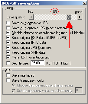
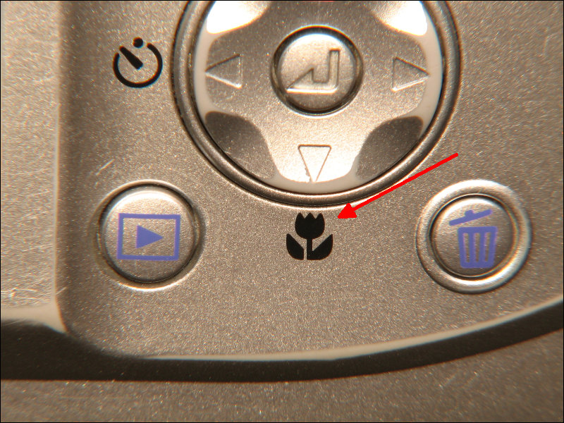
 It's often good to crop a photo. If you only need to post a section of the image you captured or you want to remove something from the image, you can use a program like Irfanview. It's a free download and very easy to use. After downloading the program, you open the image in Irfan-View, drag a rectangle around the area you want to keep and hit ctrl-y. This removes everything that's not in the selected rectangle. Then you simply save the image. To reduce the file size with virtually no reduction in quality, set the JPEG 'save quality' to about 85. If you'd like more information on the capabilities of Irfan-View, you can find it on my computer site. Resolution: Virtually all cameras allow you to select the overall resolution of the image. For most cameras, a resolution that produces an image that's 2000 to 3000 pixels wide is a good choice (common resolutions in that range are 2048x1536, 2816x2112 and 3264x2448). Unless the photos is very good and only includes a few closely spaced objects, the minimum resolution (often 640x480) is useless. Macro or Normal Mode: You'll have to try your camera in both normal and macro modes. Some cameras (like the Olympus C-740 that you'll see here) work better in normal mode. The Nikon 2200 (also used here) works better in macro mode. To switch to macro mode, look for the button or setting that looks like a tulip/flower. That's the universal symbol for the macro mode. Angle at which Photo is Taken: Most people try to take photos with the camera body (film plane) parallel with the circuit board. With proper (advanced) lighting techniques or natural/ambient light, that may be ideal. When using an on-board flash for lighting, it's generally not a good idea. Take the photo at a slight angle. Try several angles to see which works best. You want the least angle possible without having the flash reflect off of the board and back into the lens. Flash or No-Flash: In general, it's necessary to use the flash to get good photos. Without the flash, the camera will slow down the shutter to produce acceptable exposure and the photo will be blurred unless you use the timer and a tripod. If you can't get good photos with the flash, you can use sunlight to get enough light to allow the camera to set a higher shutter speed. Don't use direct sunlight. If there is a cloudy overcast, you can take the photos without any cover. If there is no overcast, you will need to be under-cover (like a carport). Zoom Range: Most cameras have a zoom function. The image quality is generally better near the center of the zoom range than it as at either extreme. When framing the image, set the zoom to the middle of its range and move the camera back/forth to photograph the area of the board that you need help with. Auto or Manual: For those not familiar with their cameras, the full auto mode should be tried first. Some cameras (like the 2200 here) only have auto or scene modes (no fully manual mode) so there is little choice. If you're familiar with the manual modes and know how to use them, you're likely just bored if you're reading this. In manual mode, you can select the shutter speed, the aperture, the ISO and the flash power. If you can use manual mode, try to use the highest F-stop/number you can. This will provide a greater depth of field (more components in sharp focus). Using a shutter speed of at least 1/60 of a second it important to prevent motion blur (even if your camera has image stabilization). Nikon Coolpix 2200: The following camera and diffuser was used to take the next circuit board image. The simple wire frame and tracing paper are a diffuser to help make the lighting a bit more even. The photos without the diffuser were pretty good but this simple device makes them better. For those who are not familiar with cameras, the tripod socket on the bottom of the camera is a standard 1/4"-20. The screw was tightened (by hand) until it bottomed out in the socket and then the nut was drawn down on the ring terminal. The tripod sockets are typically relatively fragile plastic so you have to be very careful to avoid breaking them. 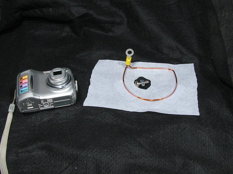 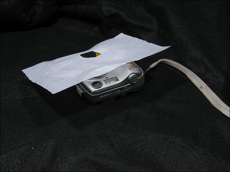 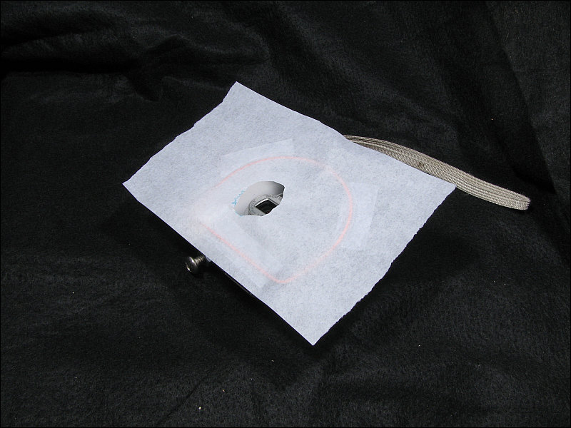 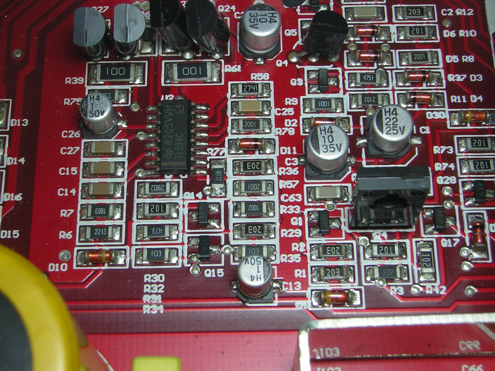 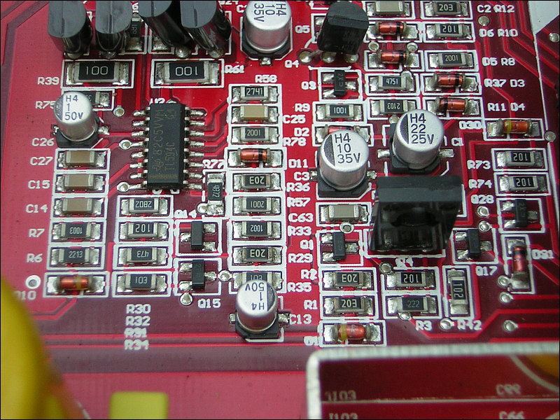 This is an old 3MP camera that I keep around to take photos of waveforms on an oscilloscope. They are available used on eBay for about $50. You should be aware that they have a problem with keeping the memory (internal backup battery is dead in most of them) but they'll work OK on full auto. They work in other modes but you have to reset all settings every time you power it up. In the first two photos, you can see the diffuser I used on this camera. The camera has an accessory lens holder (available for about $10 on eBay - buy a black one instead of a silver one) if you buy this camera or one similar (C-720, 730, 750, 760). Again, I used a diffuser. This is another simple and cheap device that makes the photos much better. 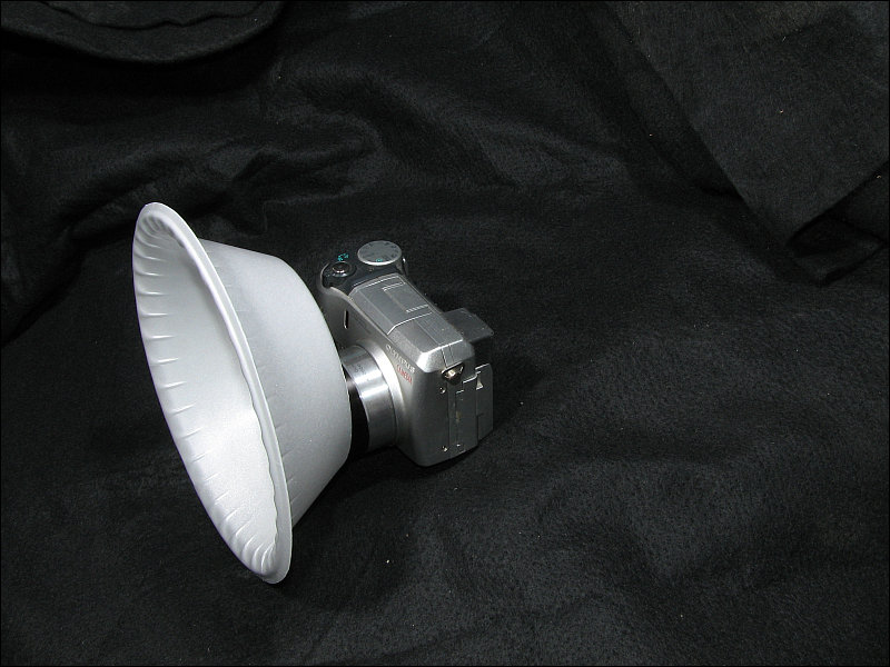 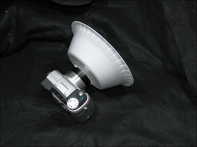 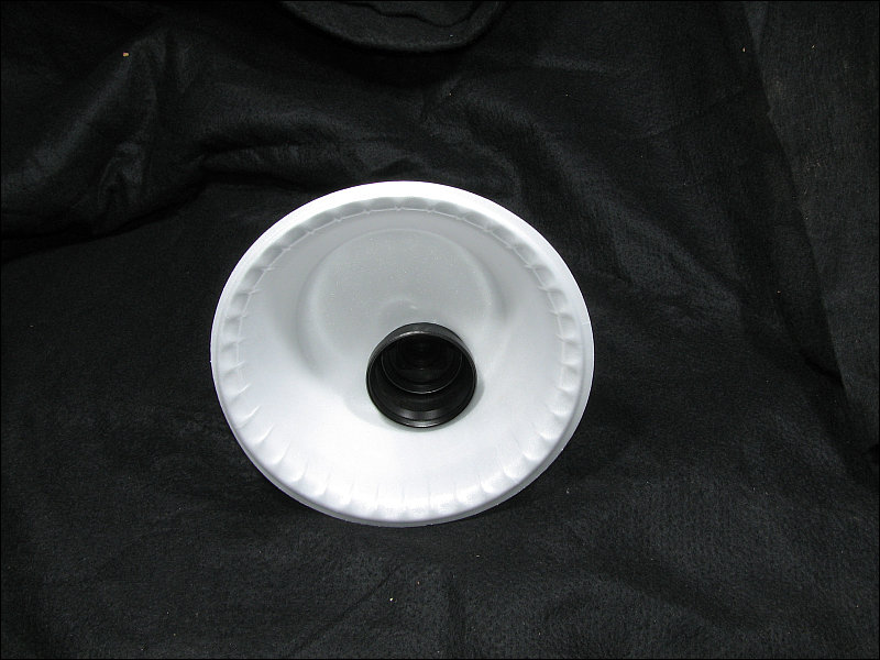 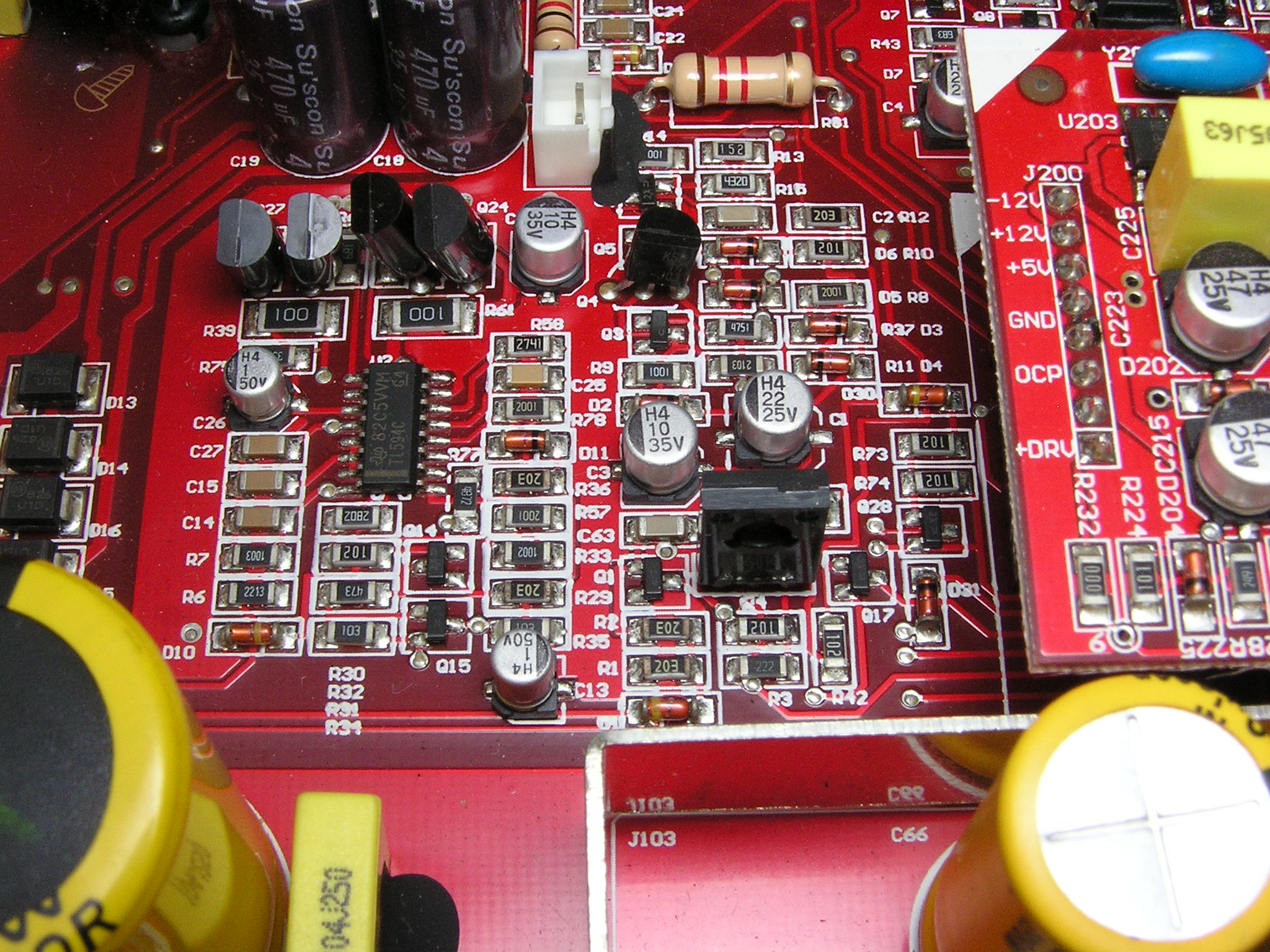 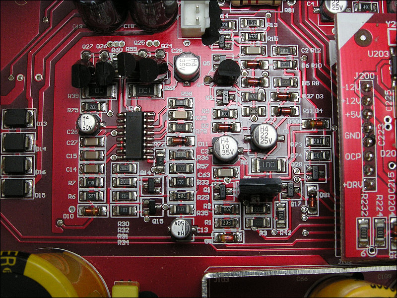 This is a good camera but not really well suited for this type of work unless you have accessory lenses and the required adapter. The macro mode is useless (I can't find any difference from the normal mode) and the super-macro is only good for photos taken within a couple of inches. To take photos with this camera, the amp has to be about 3 feet away from the lens. This means that the amp has to either be propped up so you can step back and photograph it or you have to place the amp on the floor and photograph it. Here, I used another soup-bowl diffuser. I couldn't use the full auto mode with this camera. I had to use the manual mode setting the aperture and shutter speed to get the right exposure. 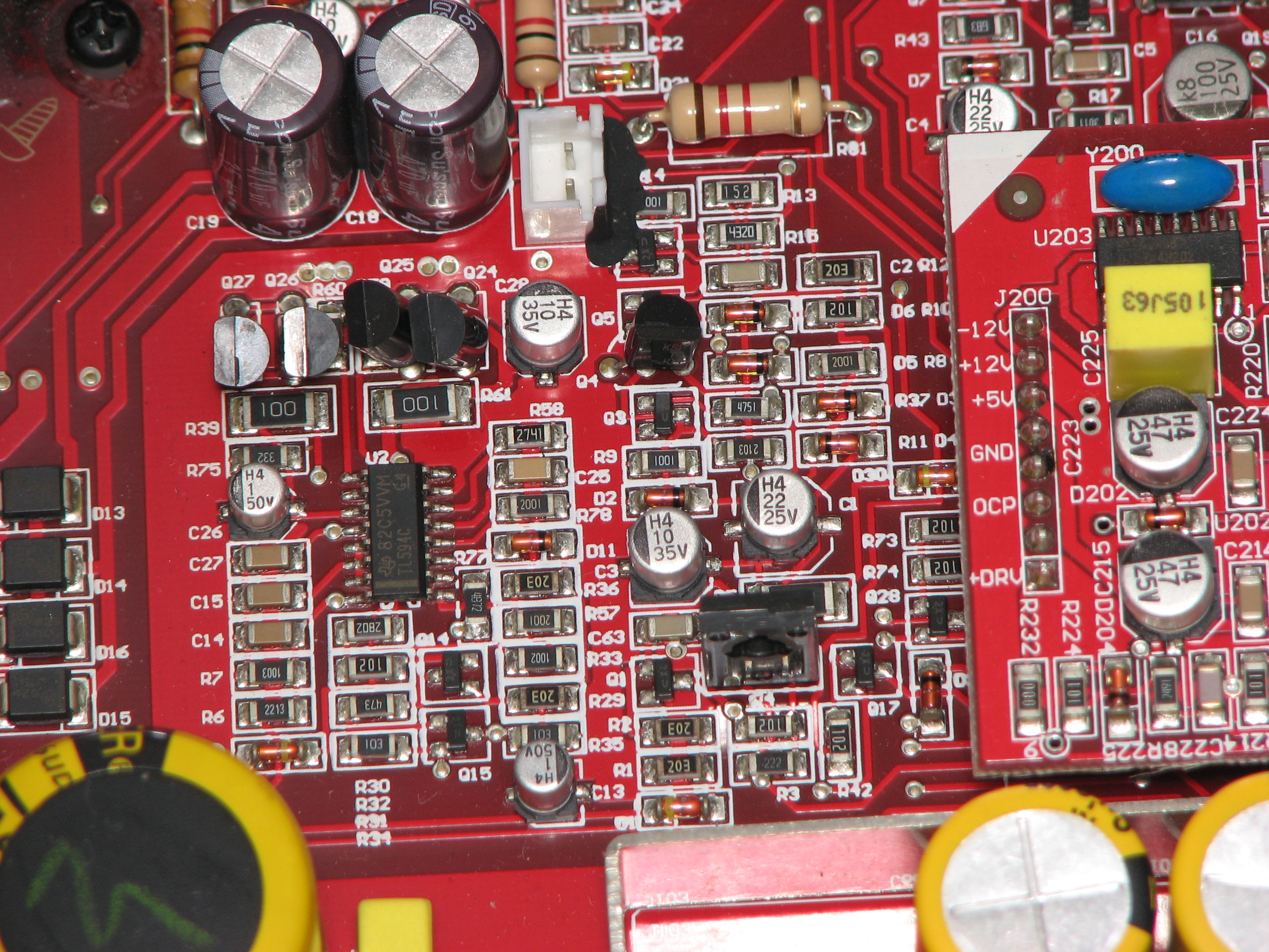 Tips for Email or Forum Posts when Asking for Repair Assistance
For those who read this and see something that they've done and think I'm singling them out, rest assured that I'm not. Nothing is here because it happened one time. If it's here I've seen it so many times that it's gotten annoying and this is an attempt to prevent seeing it again. When asking for help, take time to think about the problem and include all information that you think is relevant. Putting forth a bit of extra effort could mean the difference between getting the desired answer in a few minutes or having it take a few days (or longer).
Reducing Variables When Troubleshooting:This has happened enough times that I'm placing it at the top of the list. For some reason, people are using the gain controls to adjust the level when working on amplifiers. As an example where this causes problems... Let's say that the amplifier has a problem when the output reaches a certain level. The person asking for help states that the amp shuts down when the gain is set beyond a certain point. Does that mean that there is a problem with the gain control (the amp could begin to oscillate due to an open connection in the pot) or with something that's causing the amp to shut down when the output reaches a certain level. If they left the gain in one position (max gain recommended), the person helping to repair the amp wouldn't have to be concerned with the gain control and wouldn't have to waste time asking questions to rule it out. Remember, when posting questions on forums or repairing via email, it can take 24 hours or more between the question and answer. Having to rule out just a few things could add days or more to a repair. Posting Photos: You should understand that no one can know what every amp looks like so it may not be possible to help with every repair. It's also possible that no one will be familiar with the make/model amp you have. Fortunately, a lot of amps are clones and if someone sees the inside of your amp, they may be able to help, even if they've never had the exact model you have on the bench. When you start a forum thread, include photos of the main board (at the very least). If it uses daughter boards (boards attached to the main board), include photos of those as well. Do you best to make the photos you post as good/useful as they can be. Post at relatively high resolution (at least 800 pixels wide). Most cameras produce images at least 2000 pixels wide so you probably won't have an excuse not to post decent size images. When posting the image, orient the camera so that the amp is displayed lengthwise through the longest axis of the frame of the camera. The next image is what NOT to post. Not only is the image too small, it doesn't make the most of the frame of the camera.  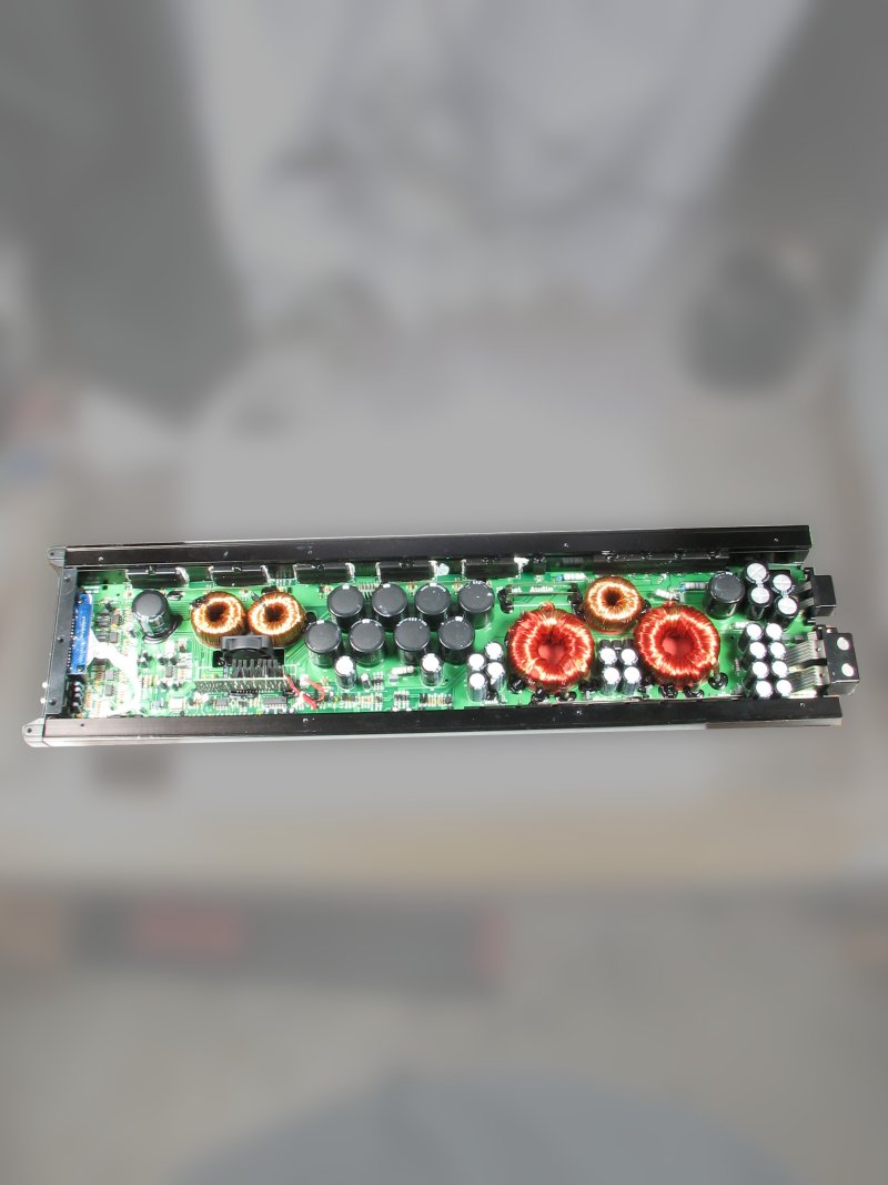 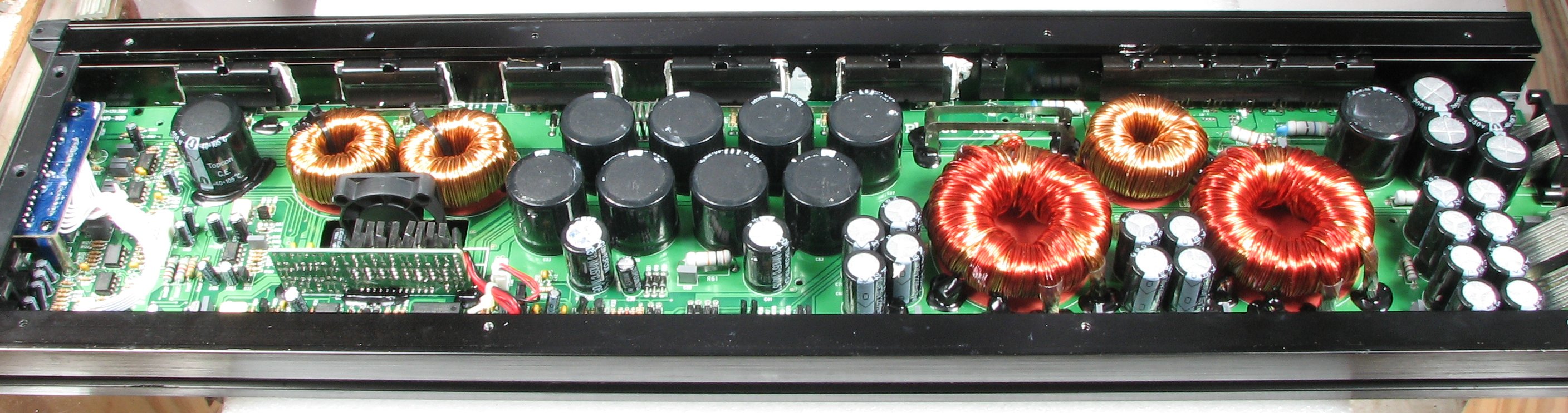 One of the most important things you need to do when asking for help is to use proper grammar. This includes punctuation, capitalization and proper spelling. It may seem like I'm being unreasonable asking for this but this is technical and the language needs to be precise so I don't have to ask for clarification of everything you send me. As a general rule, you should attempt to write at approximately the same level as the person with whom you're corresponding. If you're in a forum where there is nothing but slang, then it's appropriate for you to reply that way. If the person corresponding with you is taking the time to use proper grammar, punctuation, capitalization and paragraph breaks, you should do the same. I'm willing to help just about anyone (free of charge) but you have to do your best to help me to help you. If this is too much to ask, please look for help elsewhere. If you're from somewhere other than the US and/or English isn't your native language, do your best and I'll try to help. There will be times when a mistake (slipped probes, overheating components that fail...) will cause components to burn. If a component burns beyond recognition and no one can tell you what it was, the amp may have to be sent back to the manufacturer for repair. Before you do anything to the amp, remove the cover and take photos of all of the components from all angles in good light. Check the photos on a laptop or desktop computer (large, high-quality monitor) so you can confirm that they're in focus. Save a copy to the computer. When posting on the forum, post a single, good quality photo of the entire board. Many amps are clones of other amps. If someone isn't familiar with the make/model amp you have, they may be familiar with a clone of the amp and will be able to help you. If you ask me for help and use chatspeak, LEET or truncated/abbreviated words (ur for you are, str8 for straight, etc...), don't expect me to reply. If I do reply, it will likely be to ask you to re-submit the question, written properly. If you're not intelligent enough to ask properly, you're unlikely to be intelligent enough to complete the repair. Many of the replies require 10 minutes to an hour to find the answer. If you can't take the few seconds that it takes to spell out words, you shouldn't expect anyone to spend time trying to help you. If you're someone with a legitimate learning disability and cannot use proper grammar for that reason, you can still use capital letters and periods. The spell-checker in your browser will take of spelling errors. It will at least show me that you're trying. Circuit Board Designations: When asking for help on the forum or via email, please use the circuit board designations when referring to components on the board. If you say 'the transistors on this side of the board do this' and 'the other ones do this' it gets very confusing to those who are trying to understand, via this very vague description, what you're trying to say. The components will generally have circuit board designations printed next to them on the board. Use those designations. Instead of the previous description, you'd have something like this 'transistors Q101, Q102, Q103 and Q104 do this' and 'Q105, Q106, Q107 and Q108 do this'. I know that this takes extra effort but it makes it much easier for others to help you. In the following image, you can see that virtually all of the components have a circuit board designation. The prefix tells you what type of component it is (R - resistor, Q - transistor, D - diode, C - capacitor...). R147 is the pink resistor. R52 is the large gray resistor. Q21 and Q9 are transistors. C37 is a capacitor. 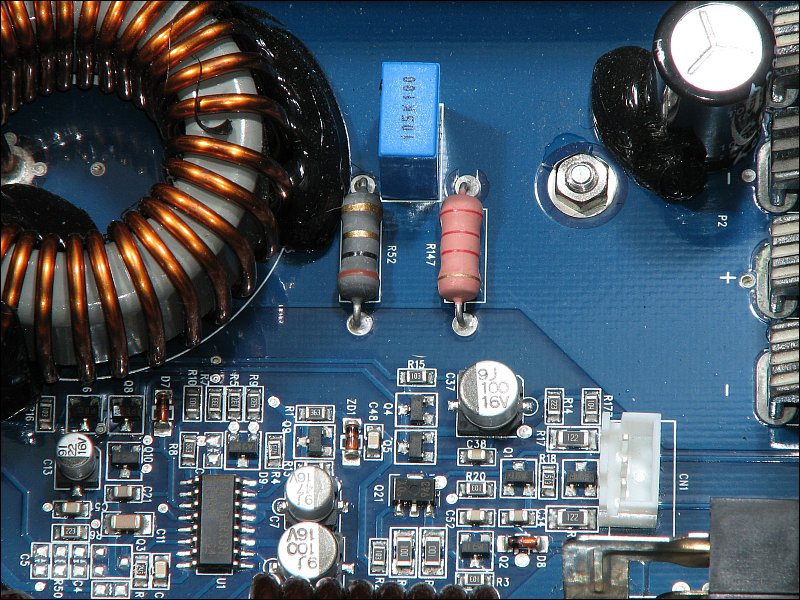 For some reason, people think that they should place the red probe on the positive terminal of the amp when measuring voltage. I would never have imagined that anyone would do this and I still can't understand why they do it but it's happened multiple times so it must be a widely held belief. The only time (that I can think of) that you would place the red probe on the B+ terminal is when you were measuring the voltage on the B+ terminal. You would have the black probe on the amplifier's main ground terminal for that measurement. When measuring most voltages, you will place the black meter probe on the amplifier's primary ground (the amplifier's main ground terminal). You'll then place the red meter probe on the point where you need to measure the voltage. Use the amplifier's primary ground for the reference point (black probe) unless otherwise instructed (for those asking for help on either the car audio forum at DIYAudio.com or via email). In some instances, you'll need to use the secondary ground as the reference. If that's the case, I'll generally tell you what point to use. The non-bridging speaker terminals (the speaker terminals that are NOT used when the amp is bridged) are often the reference point (black probe placed there) for the secondary ground. As an example, if you're measuring the voltage on the power supply driver IC (TL494, TL594, SG3525...), you'd place the black probe on the amplifier's ground terminal and touch the probe alternately to each of the pins of the driver IC. If you're asking for help and I need these voltages, I'll generally give a list for you to fill in the blanks. If it's via email, simply fill in the voltages after each pin number. If it's on the forum, copy and past the list. The list is precisely as it is for a reason. There is a blank space after each pin number to make it easier to read. If the space doesn't get copied, it's simple enough to add a space before you type the value. There is a colon after each pin number so that the person filling in the blanks doesn't use hyphens (which can be mistaken for a negative sign). There is a reminder to list the IC number (circuit board designation) if there is a chance that it will be confused with another IC. This is generally only an issue when you're listing the voltages from multiple similar ICs. Here is an example: IC# << insert IC circuit board designation here Pin 1: Pin 2: Pin 3: Pin 4: Pin 5: Pin 6: Pin 7: Pin 8: Pin 9: Pin 10: Pin 11: Pin 12: Pin 13: Pin 14: Pin 15: Pin 16: THIS is a plain text file (open with Windows Notepad) that has no formatting and retains the spaces as they should be. Right-click and save to your computer if your browser opens it and adds formatting, Copy and paste the number of pins for the IC you're measuring the voltage on. Voltage 'Across' or Voltage 'On' a Component Terminal: When you're asked to measure the voltage on a terminal of a component, you'll almost always have the black probe on a ground reference point. If you're asked to measure the voltage across a component (typically 2 terminal components), you place one probe on each end of that component. Don't give the voltage on each end of the component (with the black probe on ground) unless asked to do so because reading from ground to the two points is less accurate. If you're asked to measure the voltage with the black probe on the source leg of an FET and the red probe on the gate leg of the FET and you don't know which leg is the gate and which is the source, look up the datasheet for the FET and search the datasheet for the pin configuration. Sometimes it's near the top, sometimes it's buried in the body of the datasheet. It may take 10 or 15 minutes to do this but if you have to post a question asking which is which and no one replies for a day or the person helping you can only get to the forum once a day, it will save an entire day because you won't have to wait for an answer you can find on your own. Don't Forget the Units!: When measuring voltage, resistance, whatever... the units are VERY important. For example if you post the resistance between two legs of a semiconductor and only post '200', in most instances, that's absolutely meaningless. In most instances, 200 ohms and 200k ohms makes a huge difference. In the following images, you can see that one meter reading is approximately 3.3k ohms. The other is 3.6 ohms. If you just say that it's 3.3 it means nothing. 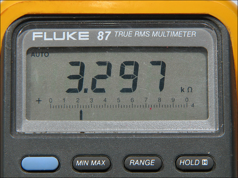  If you're trying to make measurements and you're coming up with readings that don't appear (to yourself or to someone helping you) to be correct, post a link to the owner's manual to your meter so that the person helping you can try to determine why you are getting unusual readings. If no online manual is available, post a link to a site that has a good quality photo of the front panel of the meter. The first photo you find may not be the best available. Don't be lazy (unless getting the amp repaired is not really important). Take the time to look at several pages to find the one that shows the front panel the best (all text legible). If you can take a good photo (again, take several and send the best) that's better than the ones you find on the internet, post that photo. Don't Try to Seem like You Know what You're Talking About if You Don't: When talking with friends/acquaintances on the net, you may be able to BS your way into making them think you know more than you do. When you're dealing with people who are MUCH more knowledgeable than you are about a subject and you do the same thing, you just seem like an idiot. This applies to everyone. If I went to an advanced math forum and started using terms that I didn't understand, they would think I was an idiot and if I continued to do it, I would confirm their suspicions. Don't use terms that you don't understand. If you're new to repair work and you're attempting to repair an amplifier, you're not expected to know everything. If you did know everything, you wouldn't need the help. Using the wrong term/name for a component is worse than asking what a component is, in my opinion. Intelligent, ignorant people ask questions to learn. People who want to appear to know more than they do just waste the time of those from which they're asking for help. Those who don't understand that intelligent people can be ignorant, don't know the definition of ignorant. Ignorant means that you don't know. We're all ignorant of something. Datasheets for Replacement Parts: In most cases, it's best to use the exact replacement part when repairing an amplifier. Sometimes very slight differences in parts can mean the difference between an amp working and not working properly (<< especially true for output FETs in a class D amplifier). When the original parts are no longer readily available, you may need to use a substitute part. If you have a part that you'd like to use as a substitute, post the datasheet (or a link to the datasheet) for both the original and the substitute part. Not Everything is a MOSFET: Not all of the components clamped to the heatsink are going to be the same thing. Some people (a lot of people) refer to all of the 3-legged components on the heatsink as MOSFETs. Some are rectifiers, some are transistors some are regulators. The transistors can even be used as regulators. The components that are transistors can be FETs (MOSFETs) or BJTs. If you call something a MOSFET and you're actually referring to a different component or a different type of component, the person helping you may believe that you know what you're referring to. If you're actually calling a BJT (often used for output transistors) a MOSFET and the amp has only FETs in the power supply, it will be confusing and will waste everyone's time. Don't try to be a know-it-all. No one knows everything and when you're beginning a new hobby/trade, you're not expected to know anything. IGBTs: Above it was stated that not everything is an FET. Well... Far fewer things are IGBTs in car audio. There have been quite a number of questions about IGBTs when asking for help with repairs. I'm not sure where this is originating but IGBTs are extremely rare in car amplifiers. I've only seen them in a few diagrams. I've never had to repair one and I don't remember more than one amp in all of the requests I get for help that actually used them. When asking about a type of device, look up its datasheet to see if it's an FET, A BJT (bipolar transistor) or actually an IGBT. Posting Links: Many times, when you copy a link from the address bar (especially for something found via the search function on a site), the link will only work from the browser that was used for the search. There are a couple of ways to confirm that the link works universally. The best is to open a different browser. If you're using Firefox, open IE or Chrome. If you're using IE, open Firefox or Chrome (you get the idea) and open the link in the other browser. If the link doesn't work in the other browser, it won't work for others. Opening a second tab in your current browser or opening a second instance of the same browser won't tell you if the link is good. Transistor Type vs Function: When referring to components like transistors, there are (at least) two ways to do it. You can refer to the transistor by its type (FET, BJT, JFET...) or by its function in the circuit. For example, an FET could be used in the power supply or in the output stage of the audio power amplifier. If they're used in the power supply, you'd likely refer to them as power supply transistors or power supply FETs. If they're in the output stage of the audio amplifier, you likely refer to them as output transistors or output FETs. If a smaller transistor is driving a larger transistor (or a group of larger transistors), you generally refer to them as driver transistors. These are almost always BJTs so it's not necessary to refer to them as driver BJTs. Side Note:
BJTs are often referred to simply as bipolar transistors.
State ALL Work Previously Done to the Amp:When asking for help, be sure to list ALL work that you've done to the amp. List EVERYTHING, no matter how insignificant it seems. Also list all work that appears to have been done to the amp previously. Many times, the (only) fault is due to a mistake made during the previous repair attempt. Don't Reinstall/Remove Parts Without Letting Others Know: If you're asking for help and are too impatient to wait for further instructions, don't remove or reinstall parts unless you let those trying to help you know what you've done. If you say that you've removed x-parts and reinstall them without letting others know, the next instructions could be with the assumption that those parts are out of the circuit. This could make a huge difference in the readings and may take several postings/emails to discover. Depending on how busy the person helping you is, that could mean a day or even a week wasted. If you don't know what you did last (with regards to the repair on the forum or via email), re-read the thread. Don't Break an Email Thread/Chain: If you're emailing me (or anyone who can help you), maintain an unbroken chain of emails. If you start a new email every time you ask a question, it's very difficult for me (and likely others) to remember what was previously done or even what amp it is. For you, it may be the only repair that you've dealt with and therefore relatively fresh in your mind. For someone that helps a lot of people with repairs, it won't be so fresh. I may have more than 100 emails and forum posts in the matter of a few days. In a day's time, I probably won't remember much of the repair and after a week, it's unlikely that I'll remember any of it without skimming over the unbroken chain of messages. If you continue to break the chain of emails, I'll stop replying. I try to help as many people as possible and if you won't cooperate, I can't help you. If helping one uncooperative person prevents me from helping 3 others due to time wasted, it's not fair to the others. If you have a thread or email chain that you've started for one amp, don't ask questions about another amp in that chain/thread. Start a new chain/thread and include the make/model of the amp in the subject line of the message. Each time you start a different repair, start a new chain/thread. On the forums, do not ask questions about your amp in a repair thread started by someone else with a similar amp. Start your own thread. It gets very confusing, especially if the original poster has additional questions about their amp. If you're not intelligent enough to start a new thread, there's a pretty good chance that you're not intelligent enough to repair your own amp. Problems Concerning Noise or Distortion: If you ask for help with a repair, you need to be very clear about the problem, especially when it concerns noise or distortion. Noise and distortion should be treated differently when asking for help with a repair. Distortion makes the output less clear, harder to understand. If your amp only distorts as the output increases (but well before you think it should), you need to confirm that the DC voltage across the B+ and ground terminals of the amp (multimeter probes placed directly on the metal part of the B+ and ground terminals on the amp) is remaining at or above 12v. If it's dropping lower, that could be part of the problem and you need to determine why it's dropping. Is it distorted at all output levels or only at higher output levels? Is only one channel distorted or are multiple channels distorted? Does changing the position of any of the controls make a difference in the quality of the output? When checking this, you need to have a speaker connected to the channel that's defective, listening carefully while operating all controls through their entire range. If the audio becomes clear in one position (even intermittently), you need to include that bit of information when you ask for help. Note:
When it's suggested that you operate all controls through their entire range, that is in reference to the controls accessible from the outside of the amp. There are controls inside some amps that, if turned, can result in the failure of the amplifier or severe damage to the speakers. Do not adjust any internal controls unless instructed to do so. If you have made adjustments to the internal controls, you need to say so when you ask for help.
Noise:Many people use the terms hiss, hum, buzz. A hiss would tend to be a higher frequency noise. A hum would tend to be a lower frequency noise. A buzz would tend to be a mid to high frequency noise. You also need to be specific about it's relative loudness of the noise. Is it barely audible (ear needs to be almost on the speaker to hear it)? Is it moderately loud to where it would be difficult to hold a conversation over it? Is it so loud that it absolutely overwhelms any audio, no matter the volume level? Is the noise being produced only by the internal components of the amplifier or is the noise audible through the speaker as well? Many amplifier produce significant noise from the various transformers and inductors and it is often not a problem that needs to be or can be resolved. If the noise is not entering the audio signal and would not be audible when the amp was being used normally (all covers on, amp in trunk or in amp rack...), it's probably not something that you need to be concerned with. When asking for help, be sure to note whether the noise is audible or not in the speakers. Does the noise vary with a change in the position of any of the controls on the amp? Does the noise go away when no signal source is connected? Does the noise vary with the level on the signal source? Are you using a battery-powered signal source (ipod, etc...)? Are you using a test speaker appropriate for the amp that you're repairing? If you're repairing a multi-thousand watt class D amp and are using a full range speaker with efficient tweeters and hear a hiss, that doesn't necessarily mean that there is a problem. Some class D amps are noisy. If you were to connect a subwoofer, would the installed amp produce enough noise to be audible? As a side note... When using a speaker to test an amplifier, don't use an expensive or fragile speaker. To offer a bit of protection for the speaker, you should also insert a non-polarized capacitor in series with the speaker. For full range amps, a 100uf cap is typically a good choice. It will work for subwoofer amps as well but the 100uF cap will block most bass. For testing subwoofer amps, you should use a robust subwoofer and have it where you can see the cone. This allows you to quickly disconnect it if you see the cone pull in or push out due to excessive DC offset. List of Test Equipment: When you make your original post or request for help, list the test equipment that you have. Include the make/model for each piece of equipment. This will help those helping you to ask for tests that you can perform with the tools that you have. If you don't, at the very least, have a multimeter, there's really no way that anyone can help you. If you don't have a meter , don't run out and buy one blindly. Start a post asking if the meters that you're considering are a good choice. There are plenty of meters that are all but useless and there's no point in having to buy multiple meters because you made a poor choice with the first one you purchased. An oscilloscope isn't absolutely required for all repairs but it makes it easier to help with repairs that involve distorted output. You will be asked to post or email a photo of the distorted waveform. When you take the photo, you should set the camera so that it doesn't use the flash. It's not important that the face of the scope be well lit when all that's needed is a photo of the displayed waveform. You'll need to use a sine-wave for the audio source. You can download the following test tones. You'll need to either burn them to a CD or copy them to your digital audio source (MP3player, ipod...). The 100Hz is most commonly used.
I know that it may seem like I'm a bit of a jerk (others would use stronger language to describe me) but I'm quite frustrated with the younger generation. All they seem to be able to do well is to play video games. Except for a very tiny fraction of the population, that's getting them nowhere. I try to push and prod them to get motivated but it's difficult (I'm referring to those who 'claim' they want to learn). The information and suggestions on this page alone could help a lot of people make a lot of money if they take the time to read it (a good tech can make between $60 and $90/hour) but time after time, they state that they've read all of it and then ask questions that tend to indicate that they have barely skimmed over it -- at best. I've put a lot of work into this page and want people to benefit from it. The language/terms used in parts of it (the work 'lazy' keeps creeping in) may not be pleasant but it seems that too many people require stronger language to motivate them. Oscilloscope Comparison
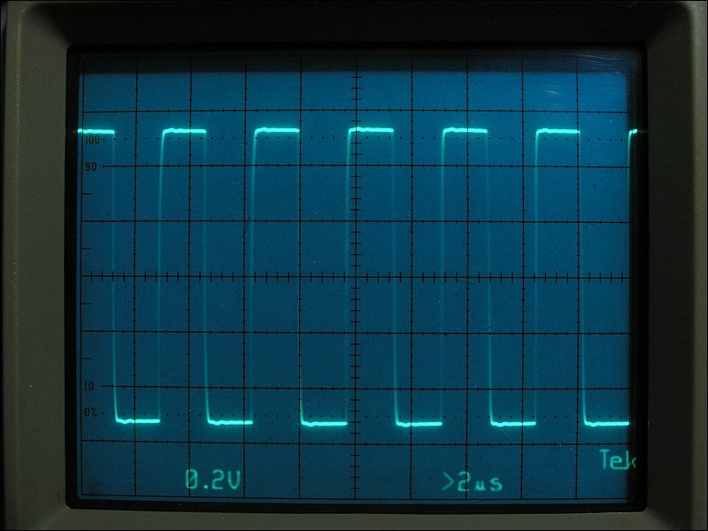
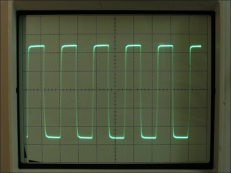
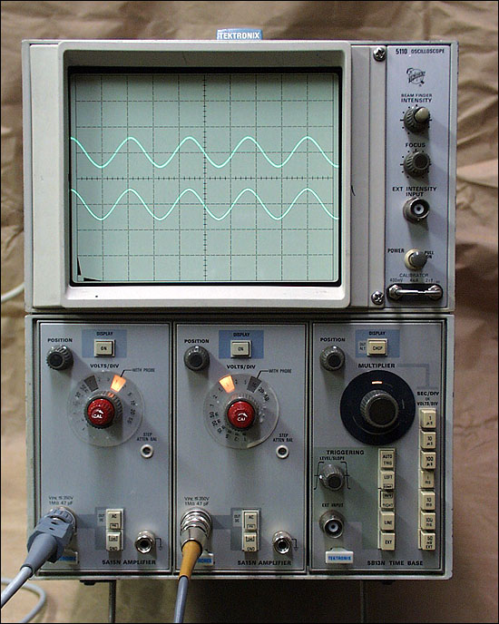
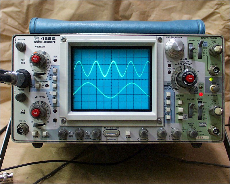
There have been a lot of questions about the type of scope necessary to do this type of work. Many people are under the impression that they need an expensive 100MHz scope to troubleshoot audio circuits. That's simply not the case. Below, you can see two different scopes. The first one is a Tektronix 2230 digital storage scope rated for 100MHz. The second photo is the same signal displayed on a Tektronix 5110 oscilloscope rated for 2MHz (not a misprint, 2MHz). Although the 2230 has slightly better resolution, the 5110 has good enough resolution for virtually any problem that you'll encounter. The signal is a 160kHz square wave. This is typically the highest frequency you'll find in the audio section of most class D amps. Some full range class D (T) amps operate at higher frequencies but those amps are not common. Even those amps that operate at higher frequencies operate well below 1MHz.
  Counterfeit Semiconductors
When buying semiconductors, you should only buy from reputable distributors. There are quite a few counterfeit/fake components on the market. Sometimes, the counterfeiter will buy cheap components and re-mark them. Others could simply be manufactured with very low standards. If you have an amp that fails repeatedly after repairing it and you suspect that the transistors may be fakes, break open the package and compare the size of the silicon die to those in the following photos. If your transistors look like the die has been glued to the tab or the die is significantly smaller than the ones in the photos below (for the same part/manufacturer), you may have counterfeit parts. You can send the parts to the manufacturer and they will be able to determine if the components are genuine or counterfeit. I believe that the transistors below are genuine components unless otherwise noted.
Plug Configurations for Older Amplifiers
  Alpine MRP-M1000
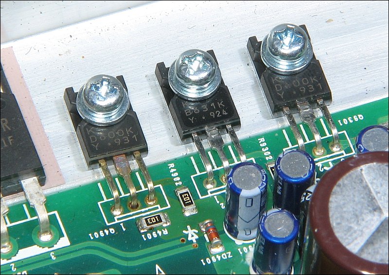
I have received more requests for the service manual for this amp than any other. The problem is virtually always the same. Q4901 has failed or the amp is non-functional with no blown power transistors (output or power supply). The problem is generally Q4901. This transistor is the voltage regulator for the drive circuit for the class D amplifier circuit. When it fails, the drive circuit has no supply voltage so it cannot function. If you're lucky, it has failed alone and replacing it is all you need to do. The original transistor can be sourced from PacParts.com. The KSC2690A can be used as a substitute but it needs to have a suitable electrical insulator (mica, Kapton...) installed between the transistor and the heatsink.
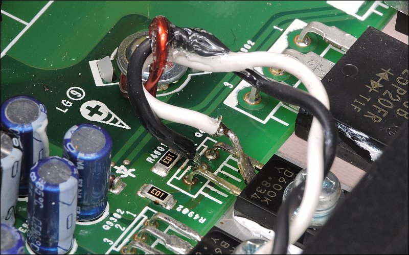
The transistor fails because it runs too hot. That's because it's being asked to dissipate too much power (in the form of heat). To make matters worse, Alpine assembled the amp without applying heatsink compound under the transistor. Yet another problem is that the heatsink has a high spot where the screw is threaded into the sink. Knocking down the high spot and applying compound can make the transistor more reliable but it still runs very hot. It's far too hot to hold your finger on but generally cool enough for the transistor to survive. One of the tell-tale signs that a semiconductor has run hot for a long period of time is it's color. Many times, the black plastic turns brown. As you can see below, Q4901 has a brown tint compared to the other D600 transistor. You can also see that the leads have become discolored due to heat.
 Note:
The following has been tested but not extensively tested. Use it at your own risk.
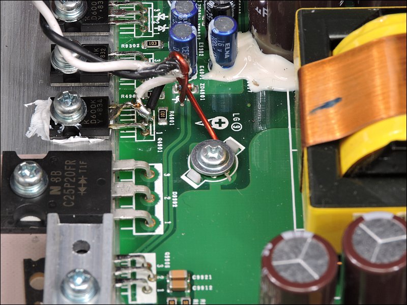
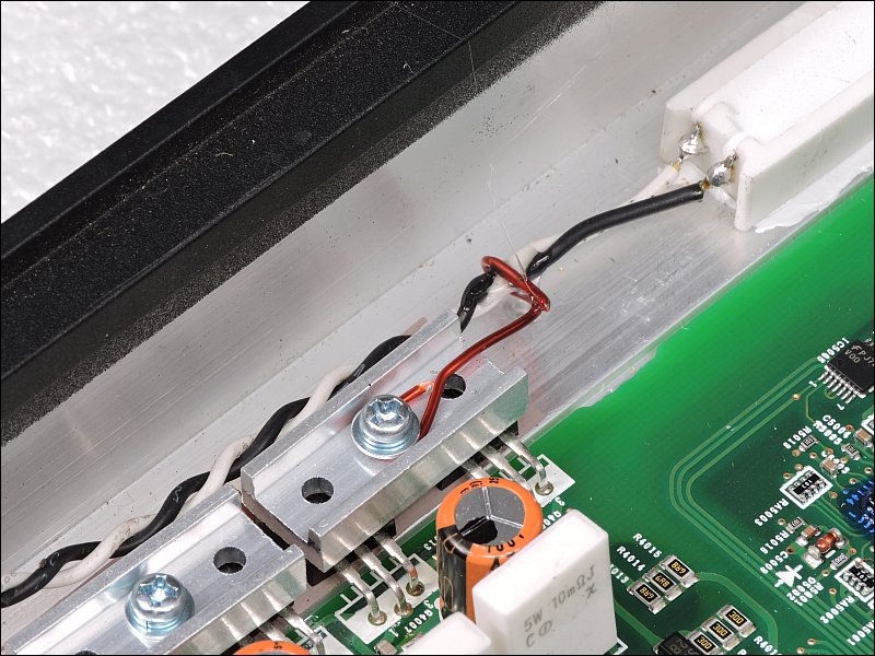
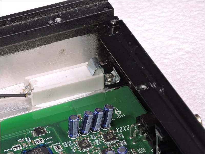
A slightly more complex solution is to insert a 'dropping' resistor in series with the transistor. Power dissipation is determined by the voltage across a device (the transistor) and the current flowing through that device. To reduce the power dissipation, you have to decrease at least one of the two. Inserting a dropping resistor reduces the voltage drop across the transistor (some is dropped across the resistor before transistor). When doing this, you have to be certain that the voltage isn't dropped to a point to where it affects the output of the transistor and doesn't exceed the power rating of the dropping resistor.
The following image is a wide-shot showing the transistor to the resistor that was added. More detailed photos will follow.
 Note:
The term 'dropping resistor' describes the function of the resistor. It's not a special type of resistor. It's a general purpose resistor used to drop voltage in the circuit.
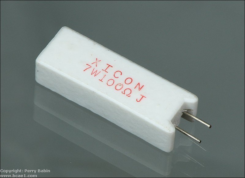
For this amp, a 47 ohm 7 watt resistor was used. It just happened to be what I had on hand but worked well. The following is a 100 ohm version of the same type of resistor (photo from 'resistors' page of this site).
     The service manual voltages are wrong because they have the wrong pin configuration. The collector is at ground. The base is about 12v above the negative rail. The emitter is about 11.5v above the negative rail. You can place the black probe on the center leg of the negative rail rectifier adjacent to Q4901 to check the base and emitter voltages. The Zener should have 12v (±10%) when the voltage is measured directly across it. The anode should be directly connected to the negative rail. The cathode is directly connected to the base of Q4901 (3rd leg). The collector of Q4901 is directly connected to ground (primary and secondary grounds are tied together). The emitter of Q4901 is directly connected to pin 3 of the IR2010S ICs. You should read approximately 11.5v between pin 15 (black probe) and pin 3 (red probe) on the IR2010S ICs. The same voltage can be read across C9801 and C9802 or across the pads for E9801 and E9802 which are not installed.
Note to self
Use http://www.bcae1.com/repairbasicsforbcae1/repairbasics.htm#rtoroscillation for a direct link to this point in the page. Rail to Rail Oscillation
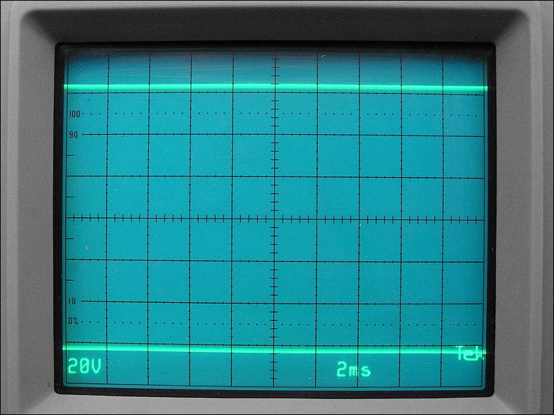
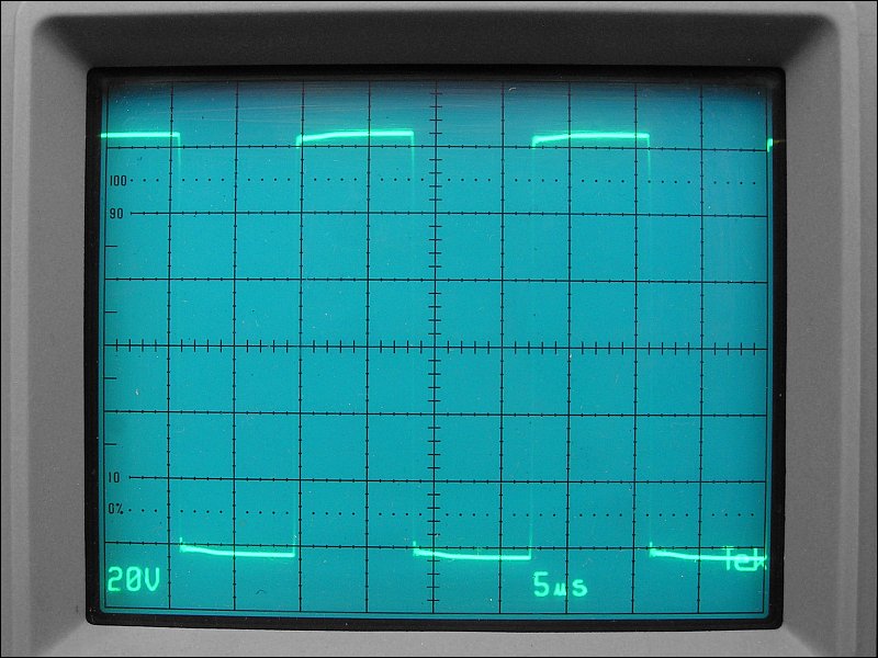
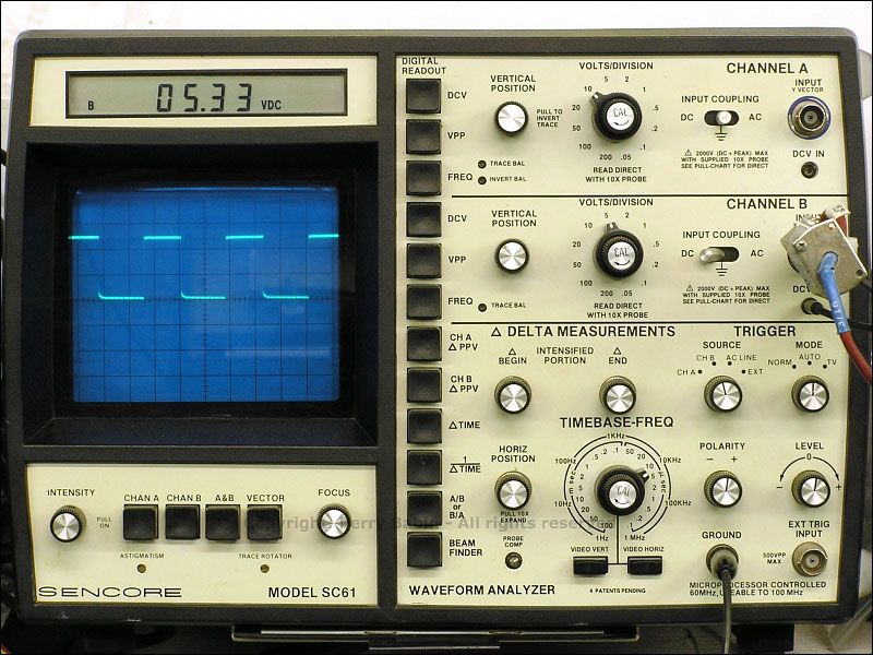
When repairing class D amps, one of the questions you're likely to get is 'does the amp have rail-rail oscillation on the output transistors for the class D amp section'. It's sometimes difficult to explain what this is and posting photos for every time the question is asked is too time consuming. The following photos are for those who don't understand R-R oscillation. The first shows the scope with DC coupling (read the 'Oscilloscope' page of this site if you don't understand 'coupling'). This is the positive rail voltage. The negative rail voltage would be the same distance below the reference line as this is above the reference line.
Updated January, 2025
Actually, it's updated virtually every day.
|

|
This is a link to this site's home page. |

|