
|
| Email Home Page |
|
|
|
|
| Email Home Page |
|
|
|
Resistors are passive electronic devices that either limit current or allow for a drop in voltage. This page will cover some of the most common types of resistors and will show you how they work in a circuit.
Schematic Symbols: 
Resistors as Current Limiting Devices:
Resistors as Voltage Dividers:
Resistor Specifications:
Note: If an ideal piece of wire (no resistance) is connected to the ideal battery (no internal resistance) as shown by the orange line, there would be an infinite amount of current flow through the wire. In the real world, the battery (like your car battery) would force enough current through the wire and create enough heat in the wire to, at the very least, melt/burn the insulation off of the wire and more than likely incinerate anything that comes in contact with it. If the wire were so large that the battery could not cause it to overheat, the battery would likely overheat and fail. This type of short circuit can easily cause 500+ amps of current to flow. For large batteries like the Odyssey PC2250, the current flow from a short circuit could be as much as 5000 amps.
----- Critically Important -----
Adobe has deemed that the Flash content on web pages is too risky to be used by the general internet user. For virtually all modern browsers, support for Flash was eliminated on 1-1-2021. This means that those browsers will not display any of the interactive Flash demos/calculators/graphics on this (or any other) site.
The simplest (not the best) fix, for now, is to download the Ruffle extension for your browser. It will render the Flash files where they were previously blocked. In some browsers, you will have to click on the big 'play' button to make the Flash applets/graphics visible. An alternative to Ruffle for viewing Flash content is to use an alternative browser like the older, portable version of Chrome (chromium), an older version of Safari for Windows or one of several other browsers. More information on Flash capable browsers can be found HERE. It's not quite as simple as Ruffle but anyone even moderately familiar with the Windows Control Panel and installation of software can use Flash as it was intended.
If a resistor is connected to a battery like shown in the above diagram, there would be less current flow than in the wire alone. How much less current depends on the value of the resistor. If the value of the resistor is 1 ohm and the battery voltage is 12 volts, according to Ohm's law the current through the resistor is 12 amps.
I=E/R
If the resistor's value is 10 ohms, with the same 12 volts applied to it, then the current flow will be less (because the resistor presents more resistance to the flow of current).
The current flow will be 1.2 amps. If you were trying to determine
the power rating needed for either resistor, you could use one of three formulae.
Using the formula P=I*E, you can see that the power being dissipated by the resistor is a product of the current
and the applied voltage. For the 1 ohm resistor, the power dissipation
is:
If you didn't already know the current flow through the 1 ohm resistor, you could use the formula P=E^2/R. This may not seem like much power but if the air flow around the resistor is restricted, it will become very hot. The 1 ohm resistor would have to be rated at 144 watts or higher to prevent its failure (from the heat generated in the resistive element).
Using the formula P=I*E, for the 10 ohm resistor, the power dissipation
is:
Using the formula P=E^2/R, for the 10 ohm resistor, the power dissipation
is:
The 10 ohm resistor would have to be rated at 14.4 watts or higher to prevent it from dying a horrible painful death.
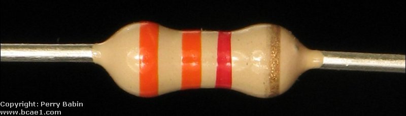
Resistor Color Codes: The most common resistors have a tolerance of plus or minus 5%. These resistors have 4 color bands. The first 2 color bands give the first 2 digits of the resistor's value. The 3rd band give the number of 0's added to the first 2 digits. If the third band is gold, you multiply the first 2 digits by .1. If it is silver, multiply by .01. The fourth band gives the tolerance. Gold is a 5% tolerance. Silver is 10%. The tolerance band is generally set off from the other bands. The other bands are generally set close together. The list below shows the values for the resistor color codes of non-precision resistors. Band 5 is rare in car audio equipment but I'll include the info anyway. The reliability of a resistor indicates the failure rate of a resistor when run at its rated power dissipation for 1000 hours. |
| Band 1 | Band 2 | Band 3 | Band 4 | Band 5 | |
| Color | 1st Digit | 2nd Digit | Multiplier | Tolerance | Reliability |
| Black | 0 | 1 | |||
| Brown | 1 | 1 | 10 | 1% | |
| Red | 2 | 2 | 100 | 0.1% | |
| Orange | 3 | 3 | 1,000 | 0.01% | |
| Yellow | 4 | 4 | 10,000 | 0.001% | |
| Green | 5 | 5 | 100,000 | ||
| Blue | 6 | 6 | 1,000,000 | ||
| Violet | 7 | 7 | 10,000,000 | ||
| Gray | 8 | 8 | 100,000,000 | ||
| White | 9 | 9 | 1,000,000,000 | ||
| Gold | x 0.1 | 5% | |||
| Silver | x 0.01 | 10% | |||
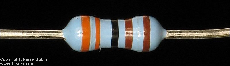
| The following chart shows what each of the bands means on a close tolerance resistor. They have an additional band which allows an additional significant digit for the value of the resistor. |
| Band 1 | Band 2 | Band 3 | Band 4 | Band 5 | Band 6 | |
| Color | 1st Digit | 2nd Digit | 3rd Digit | Multiplier | Tolerance | Reliability |
| Black | 0 | 0 | 1 | |||
| Brown | 1 | 1 | 1 | 10 | 1% | 1% |
| Red | 2 | 2 | 2 | 100 | 2% | 0.1% |
| Orange | 3 | 3 | 3 | 1,000 | 3% | 0.01% |
| Yellow | 4 | 4 | 4 | 10,000 | 0.001% | |
| Green | 5 | 5 | 5 | 100,000 | ||
| Blue | 6 | 6 | 6 | 1,000,000 | ||
| Violet | 7 | 7 | 7 | 10,000,000 | ||
| Gray | 8 | 8 | 8 | 100,000,000 | ||
| White | 9 | 9 | 9 | 1,000,000,000 | ||
| Gold | x 0.1 | 5% | ||||
| Silver | x 0.01 | 10% | ||||
|
Resistor Wattage Ratings:
 Common resistor wattage ratings are: 1/8w, 1/4w, 1/2w, 1w, 2w, 3w, 5w, 10w. There are others but these are the ones that you will likely need to use. |
|
|
|
Note: In the diagrams below we are considering the battery to be ideal, no internal resistance and always at a constant 12 volts. Current flow will be 'conventional' flow (positive to negative). Resistors as Voltage Dividers: You already know that a resistor can be used to limit the current flow in a circuit. When multiple resistors are used in series, they will divide the voltage from the power supply (a battery in this example). In this first diagram you can see that the voltage across the resistor is the same as the voltage across the battery.
Equivalent Circuits: The following 3 circuits are identical. Don't let the different configurations confuse you.
2 Resistors in Series: The resistors in the following diagram are in series. Since they are the same value (1000 ohms), the voltage drop across each resistor is the same. Each resistor drops half the supply voltage (6 volts).
 3 Resistors in Series: If there were 3 equal value resistors, the voltage would be divided equally between them. They would each have a voltage drop of 4 volts (3*4=12). As you can see, the voltage drop across all of the resistors will add up to the power supply voltage. Different Value Resistors: If the resistor values are different, you can still calculate the voltage difference across the resistors. There are a few different ways to calculate the voltage. I'll show you the most versatile way. This is the circuit:
We know:
We can calculate the current flow and then the voltage drop across the individual resistors. From the Ohm's Law page, we will use the formula:
Then, to find the voltage drop across the 1000 ohm resistor, we can use the formula:
And to find the voltage drop across the 2000 ohm resistor, we can use the formula:
The previous method (using current flow to calculate voltage drop) will work for any number of series connected resistors. There is another method to find the voltage drop across a resistor when there are only 2 resistors. The formula is:
As we found earlier on this page, a resistor can be used to dissipate power. Some people believe that they will have an increase in system SPL if they reduce the amplifier load's impedance with resistors. The fact is, the SPL will likely be reduced. Just because the amplifier is producing more power, it does NOT mean the SPL will increase. The reason? The extra power is dissipated in the form of heat and produces no audio. The reason that the SPL will likely drop is because the amplifier's internal power supply will lose some rail voltage with the lower impedance load (the loss may not be significant on amps with highly regulated power supplies). When the rail voltage drops, the output power to the speaker drops. Even if you have an amplifier with a regulated power supply and the power to the speakers doesn't fall, the amplifier will draw more current and run hotter.
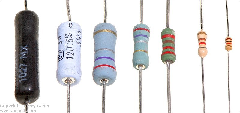
Resistor Construction:
Film Resistors:
 The resistance can be varied by varying the way the element is cut. In this diagram, you can see that leaving a wide and relatively short resistive element results in a low ohm resistor. A narrower longer helix results in a higher value resistor.
There are several different types of film resistors. The following are a few of their characterisitcs.
Carbon Film Resistors:
Metal Film Resistors:
Metal Oxide Resistors:
Carbon Composition Resistors:
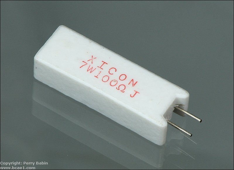
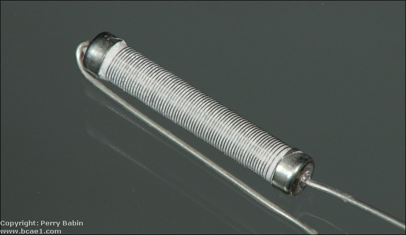
Wire Wound Resistors:
 The next resistor is a 7 watt wirewound resistor encased in ceramic. The second image is the resistor with the ceramic removed.
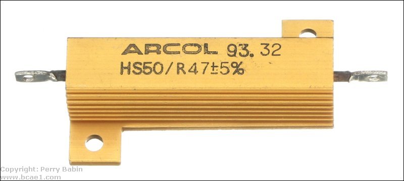
 The following type of resistor is the type most people know as a high power resistor. These resistors 'can' be used to dissipate a lot of power but they need help to do so. For them to dissipate their rated power, they have to be tightly clamped to a heatsink. Without a suitable heatsink, the resistor can only dissipate a tiny fraction of its rated power. The resistor inside the aluminum housing is much like the resistive element above. These are commonly used as dummy loads for testing amplifiers but I no longer use them. They are much more fragile than the next two resistors. Even with the heatsink, they don't handle power surges well.
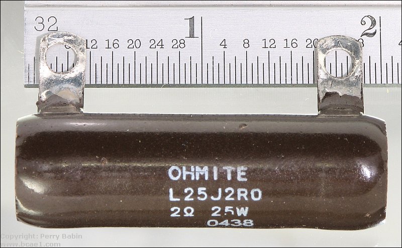
 This is a 25 watt wirewound resistor with solder lugs. Wirewound resistors like this resistor and the next one need no heatsink to dissipate their rated power. These are the type of resistors that I use for dummy loads when testing amplifiers (100+ watt resistors in series/parallel).
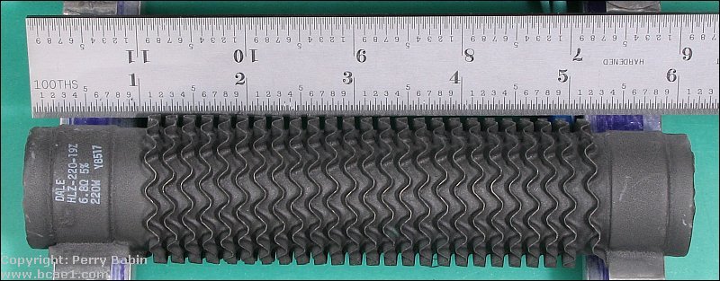
 This next resistor is a 220 watt wirewound resistor. As you can see, it's relatively large but larger resistors are readily available.
Flame-Proof Resistors:
Power Handling:
|
|
You should remember: 1. If a resistor is inserted into a series circuit, the current flow will be reduced. 2. The reduction of current flow is directly proportional to the resistance value of the resistor. 3. When current flows through a resistor, there will be a voltage drop across the resistor. 4. When there is voltage drop across the resistor, there will be power dissipation. 5. Power dissipation will cause a rise in temperature of the resistor. |

|

|
|

|