If you are interested in repairing amplifiers professionally, THIS may be of interest to you. If you're simply trying to repair your own amplifier, the information and links on this page should help you get it repaired. You can email me if you need help.
When checking transistors (bipolar or FET) with your meter set to ohms, you should not read anything near 0 ohms when the probes are touched to the terminals of any individual transistor in any configuration. If any are shorted (~0 ohms between any 2 legs of any individual transistor), they will likely be shorted from leg 2 to leg 3 but you should check 1-2, 1-3 and 2-3.
Check all of the transistors individually. If it appears that several are shorted, you'll need to remove all that appear shorted from the board and check them individually. In the case of the output transistors, if you find only 1 shorted in a group of parallel-connected transistors, you can reinstall the ones that are not shorted to see if the amp will power up. If it does, you need to replace all in that group of parallel transistors. This is generally only viable for audio output transistors. Generally, when one power supply FET shorts, all will fail and all will have to be replaced.
Notes:
-
Above, it was stated that you shouldn't read anything near 0 ohms between the legs of any individual transistor. This is the case for MOST transistors. There are a few exceptions. One notable exception is the JFET. A JFET like the J108 will read ~8 ohms between its drain and source when no voltage is applied to it's gate. These are used extensively as muting transistors in PPI amps. Other similar JFETs are used as muting transistors in various other amps.
-
If you're trying to repair an amp, please read the Basic Amplifier Repair page BEFORE attempting to do any repairs.
|
 |
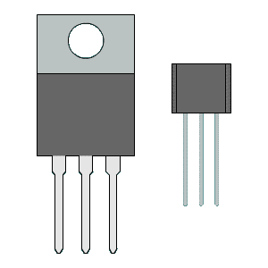
To open the bipolar transistor test form for through-hole transistors, click HERE. |
| When the window opens, click the black bar at the right of the window for instructions. | |
|
 |
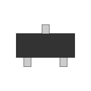
To open the bipolar transistor test form for SMD transistors, click HERE. |
| When the window opens, click the black bar at the right of the window for instructions. | |
-
You should read an open circuit when you have one meter probe on leg 1 and the other probe on leg 2 or leg 3. If you see the meter change from OL (or whatever it reads when the probes are not in contact with anything) for more than a fraction of a second, the FET is defective.
For FETs with leaky gates (defective but not quite a dead short), you will be more likely to detect faulty transistors with the meter set to ohms, than you will with it set to diode-check.
-
Connect leg 1 to leg 3 with an alligator clip lead and place the probes across legs 2 and 3. With the meter in diode-check mode, you should have a reading of approximately 0.5-0.9 with the probes one way and no reading (OL) with the probes reversed. If you don't read OL with the probes in one of the configurations (see graphic), the FET is defective.
This shows the reading with the meter in diode-check mode.
The following are some of the FETs that can be checked with this procedure.
- Mainly Used in Power Supplies
- IRFZ34
- IRFZ44
- IRFZ46
- IRFZ48
- IRF3205
- IRFP1405
- IRFP064
- Mainly Used as Audio Output Transistors
- IRF540
- IRF640
- IRFB42N20
- IRFB31N20
- IRF3415
- IRFP3415
- IRFP360LC
- FQA28N15
- FQP19N20
The following are some of the FETs that can be checked with this procedure but you'll need to reverse the leads. These are P-Channel FETs.
- Mainly Used as Audio Output Transistors
- IRF9540
- IRF9640
- IRF6215
- FQA36P15
- FQP12P20
- Links to other helpful pages:
- Testing the head unit's shield ground to make sure it's not open (a common problem for Pioneer head units) click HERE.
- Troubleshooting a system with an amp that's going into protect mode click HERE.
- Troubleshooting an amplifier that's not working and may have defective internal components click HERE for the Basic Amplifier Repair page.