
|
| Email Home Page |
|
|
|
|
| Email Home Page |
|
|
|
Foreword:
The Contacts:
The Electromagnet:
----- Critically Important -----
----- Critically Important -----
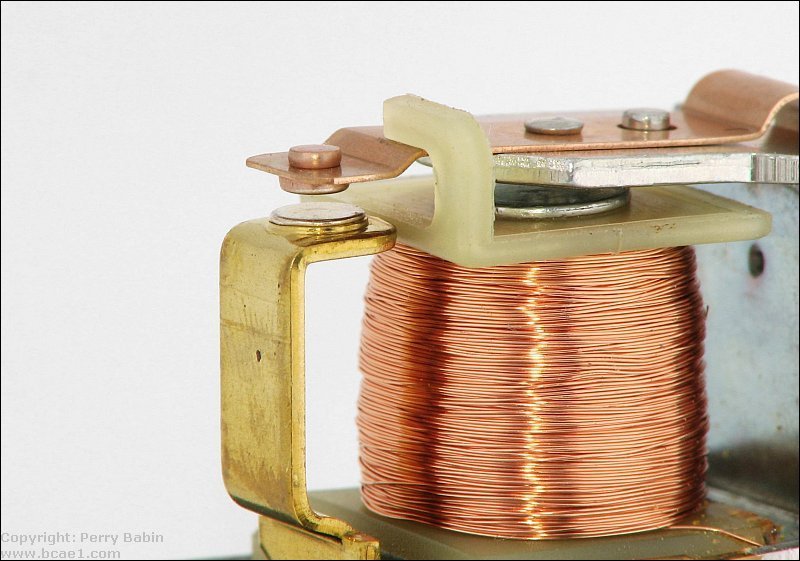
The terms 'normally open' and 'normally closed' refer to a pair of contacts in a relay or switch. For the simplest of relays (like the one in the photo at the top of the page, see close-up below), there is only one pair of contacts, the movable contact and a stationary contact. With no voltage applied to the coil of the relay, the contacts are open. If you used the relay to make/break the connection in a circuit, the connection would be broken with no voltage applied to the coil. If you had a relay with two pairs of contacts (like the one in the demo above), there would be one pair of contacts that could pass current (even with no voltage applied to the coil) and one pair of contacts that could not pass current (until sufficient voltage was applied to the coil). As an example. Let's say that you needed to control two lights, one red, the other green and the green light was lit most of the time. With a relay with both normally open contacts and normally closed contacts, you would connect the green light to the normally closed contact and the red light to the normally open contact. With no power applied to the relay coil, the green light would be lit. The red would be off. When the lights needed to switch (green off, red on), you would apply voltage to the relay coil and the relay would engage. This would break the normally closed contacts (breaking the circuit for the green light) and make the normally open contacts (closing the circuit for the red light).
 In the previous example, the green light was connected through the normally closed contacts. Since it was going to be lit most of the time, it would generally be more efficient not requiring the coil be energized. This doesn't mean that it's always best to do it this way. If there was in a situation were a loss of power or a failure of the relay would prevent the red (warning) light from lighting, it may be better to power the red light through the normally closed contacts.
Two Reasons to Use a Relay: The second reason to use a relay is to isolate two circuits. If you needed to control a very high voltage circuit with a 12 volt controller, you could use a relay. Since a relay coil is 'generally' isolated from the contacts, you typically have complete isolation between the 'input' and 'output' section of the relay. Of course, the input of the relay is the relay coil and the output would be the contacts. The table below shows just a fraction of the available relay configurations. On the relay above, there was only one movable contact. As you can see below, there are multiple sets of movable contacts on some relays.
|

|
This is a Single Pole Single Throw relay. Current will only flow through the contacts when the relay coil is energized. |

|
This is a Single Pole Double Throw relay. Current will flow between the movable contact and one fixed contact when the coil is DEenergized and between the movable contact and the alternate fixed contact when the relay coil is energized. The most commonly used relay in car audio, the Bosch relay, is a SPDT relay. |

|
This is a Double Pole Single Throw relay. When the relay coil is energized, two separate and electrically isolated sets of contacts are pulled down to make contact with their stationary counterparts. There is no complete circuit path when the relay is DEenergized. |

|
This relay is a Double Pole Double Throw relay. It operates like the SPDT relay but has twice as many contacts. There are two completely isolated sets of contacts. |

|
Yep! You guessed it. This is a 4 Pole Double Throw relay. It operates like the SPDT relay but it has 4 sets of isolated contacts. |
|
|
|||
| The following are examples of different styles of relays. When you click on an icon, the image will open in a new tab or window. When it opens, it's likely going to be smaller than actual size. For most browsers, you can click on the image to view it full size. Close that window/tab when are ready to view another example. | |||
 |
 |
 |
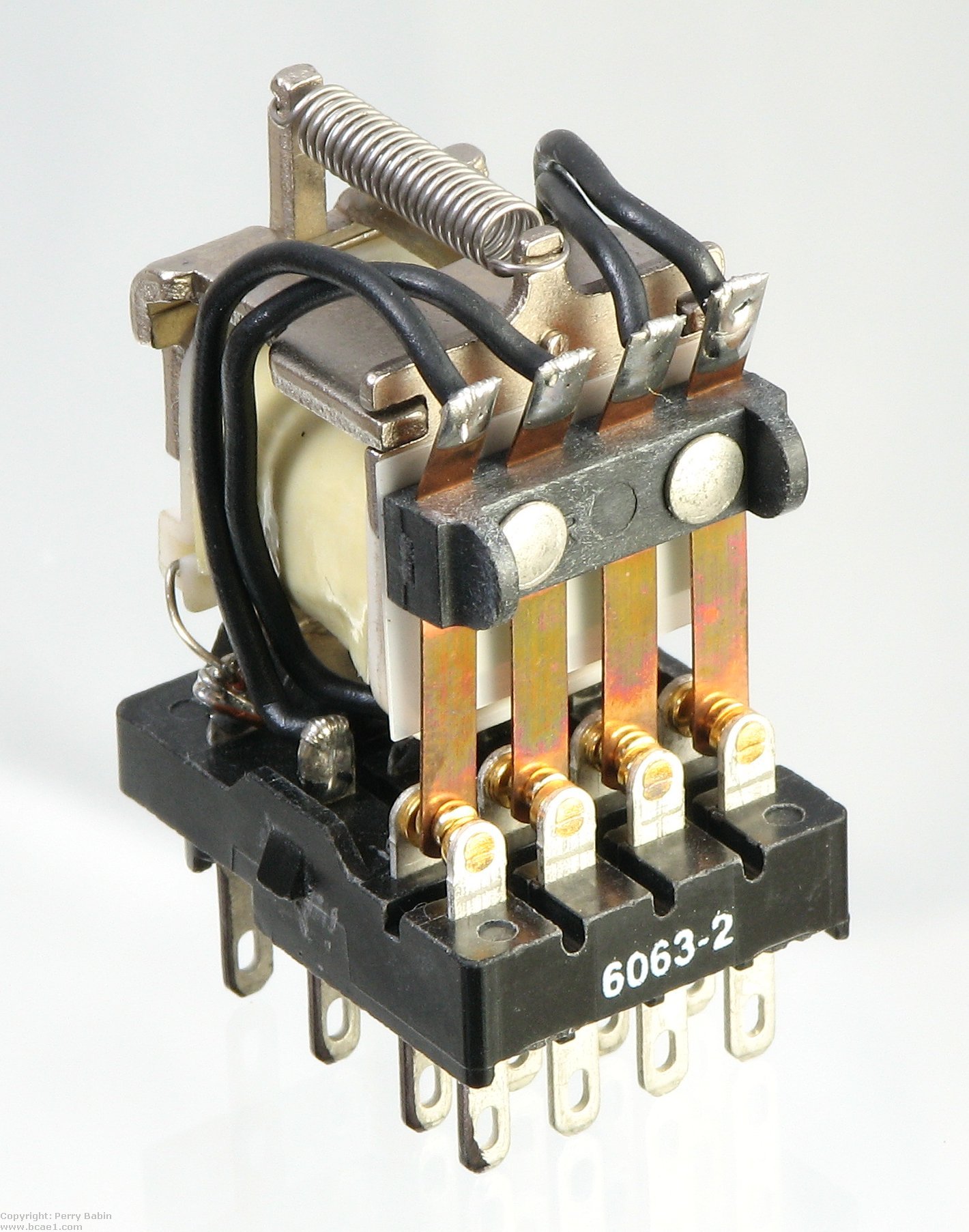 |
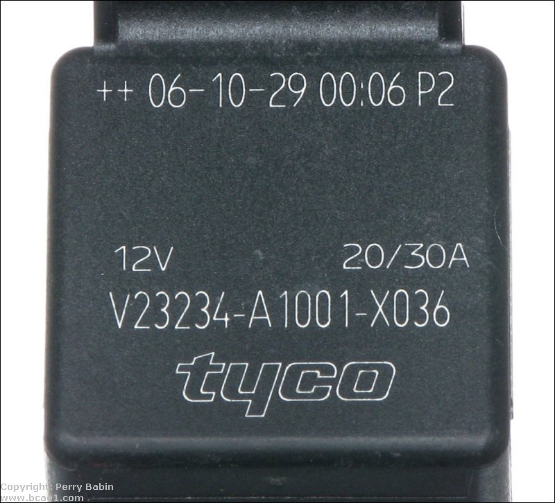
| This is a simple single pole single throw relay. You can see that there is no normally closed contact. The only time that this relay will pass current through its contacts is when the coil is energized. | This is a single pole double throw relay. This is the standard Bosch type relay. This one is made by Tyco. | This is a three pole double throw relay. The terminals on this one require that it be used in a socket. | This is a four pole, double-throw relay. |
|
There are two specifications that you must consider when selecting a relay for use in an automobile, the coil voltage and the current carrying capacity of contacts. The coil voltage for relays used in automobiles is ~12 volts. This means that if you apply 12 volts to the coil, it will pull in and stay there until the applied voltage is removed from the coil. The current rating on relay contacts tells how much current can be passed through the contacts without damage to the contacts. Some relays have different current ratings for the NC contacts (which are held together by spring tension) and the NO contacts (which are held together by the electromagnet). If you need to pass significant current through the NC contacts, you may want to check the manufacturers specifications for the relay.
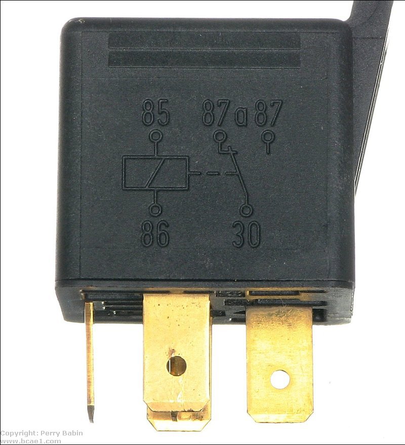
Click HERE to open this graphic in a new tab. Right-click to zoom. Left-click to drag.
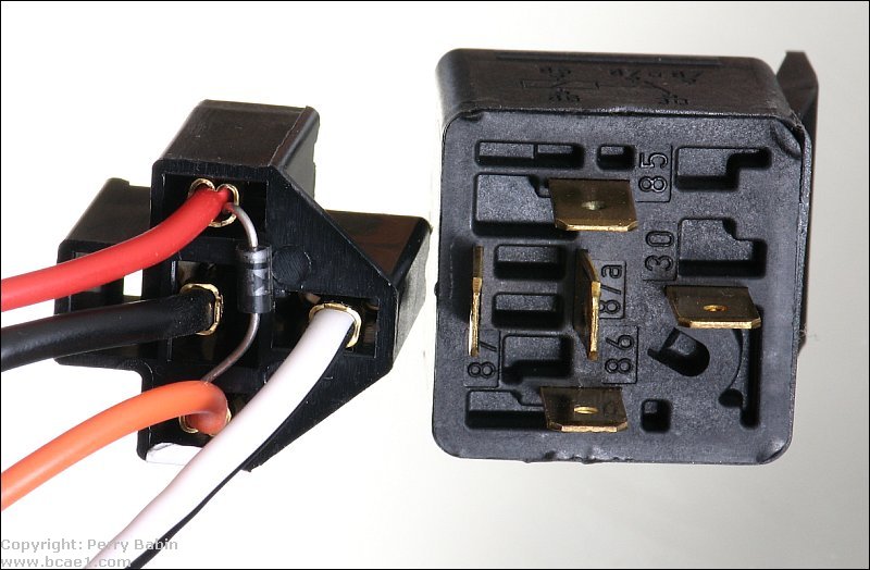
Bottom View:
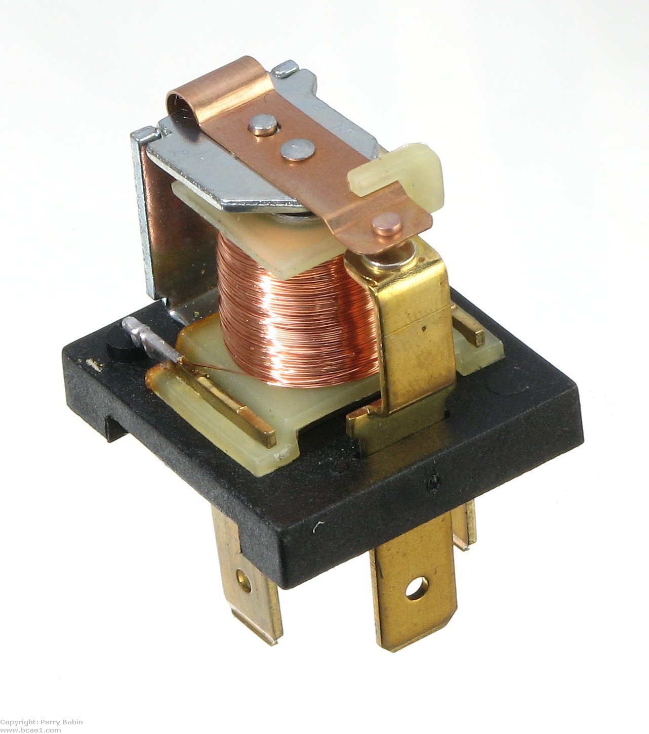
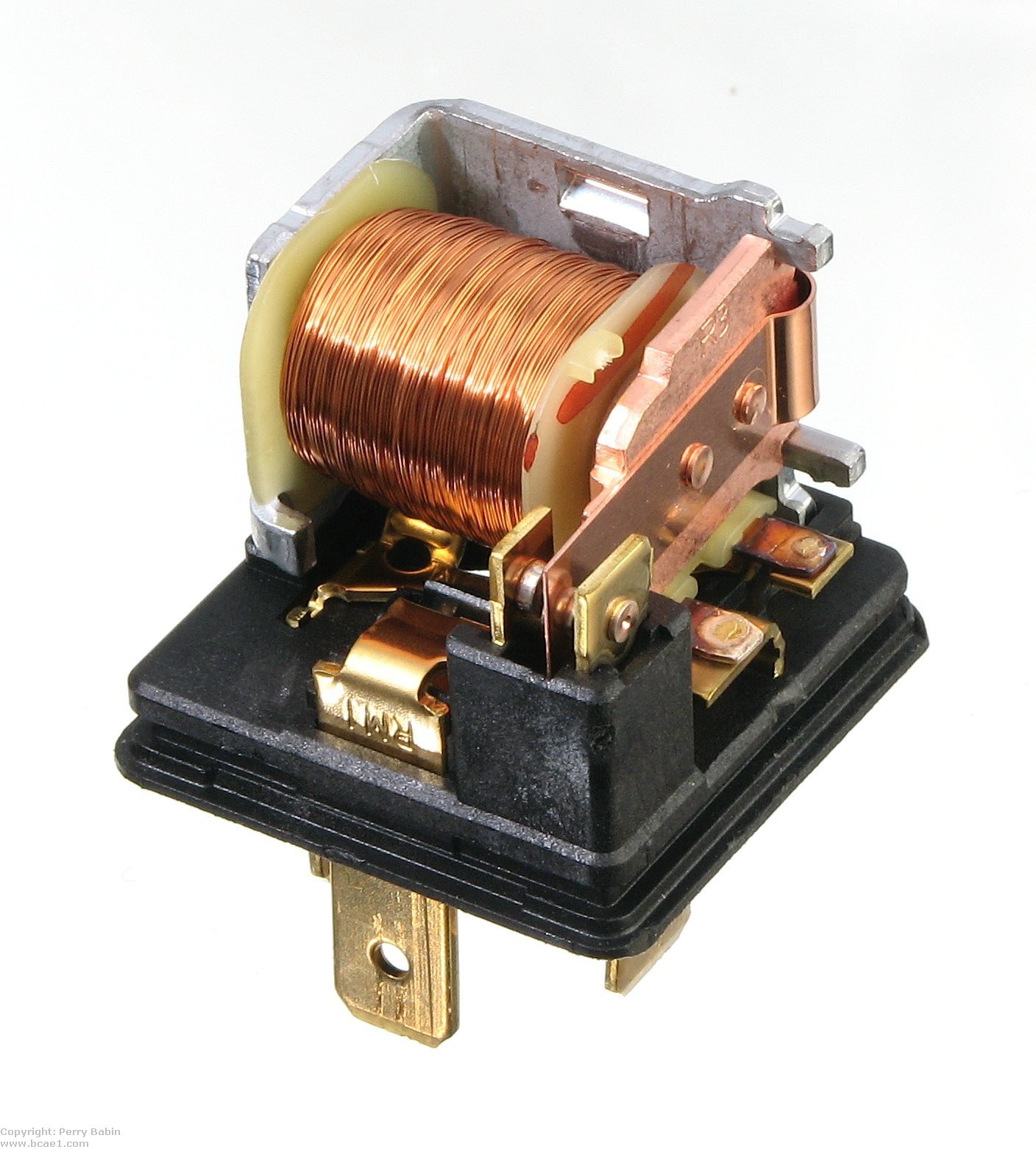
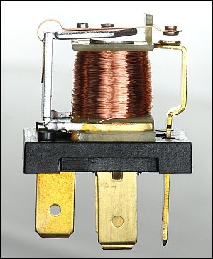
Internal Construction of Bosch relay:
Side View:
Top View:
This flash demo should help you understand how current flows through the relay as the coil is energized and deenergized.
Click HERE to make this applet fill this window.
Click HERE to make this applet fill this window.
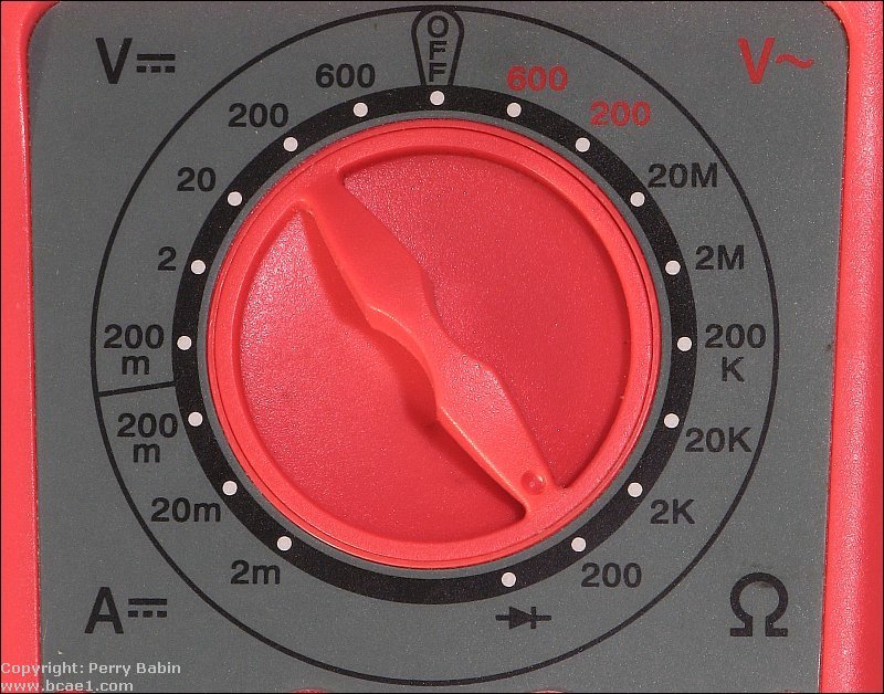
Testing Relays: Set your meter to ohms. If your meter is auto-ranging, it will have only one ohm mode and the meter will select the appropriate range automatically. If the meter is not auto-ranging, it will have several ohm ranges (like the one below). If it's not auto-ranging, set it to the lowest resistance range.
 Touch your meter probes together. What does it read? This is what it should read when the probes are placed on the terminals of closed contacts on the relay. When no voltage is applied to terminals 85 and 86, this is what you should read between terminals 30 and 87a. On other relays it will be between the common terminal and the normally closed contact's terminal. What does it read when the probes are not in contact with anything but air? That's what the meter shoud read when the probes are placed on the terminals of open contacts. When no voltage is applied to terminals 85 and 86, this is what you should read between terminals 30 and 87.
Click HERE to make this applet fill this window. If the meter isn't auto-ranging, set it to the range that includes 75 ohms. Touch the probes to terminals 85 and 86. Do you read approximately 75 ohms? If so, the coil is OK. You will do this with the relay coil disconnected from the power source.
Quenching Diodes:
Voltage Graphs:
Click HERE to open this graphic in a new tab. Right-click to zoom. Left-click to drag.
Note:
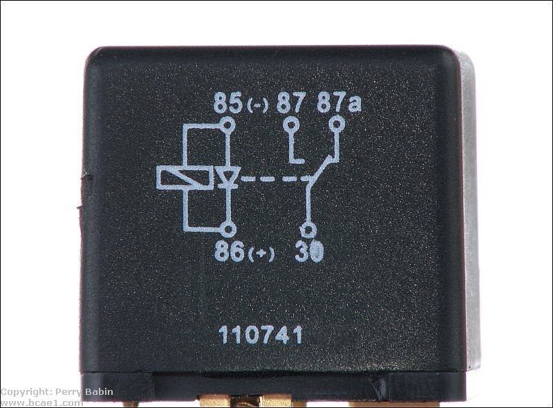
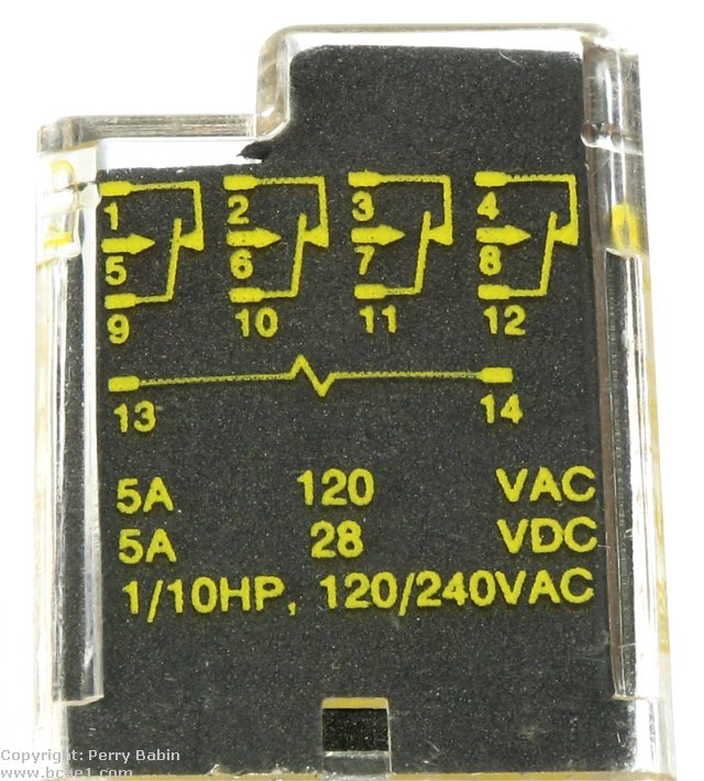
Relays with Internal Suppression Circuits: The following two images show why you need to be careful when using relays with suppression diodes. In the diagram, you can see that the anode side of the diode is connected to terminal 85. This means that terminals 85 has to be used for the ground terminal for that particular relay (this is from the Tyco datasheet). The second image shows a wiring harness for a relay that came with a car alarm. The diode is connected with reverse polarity (compared to the Bosch internal diode). Generally (maybe always with the Bosch type relays) terminal 85 is considered ground when there are internal diodes. If you were to use this relay socket with a Bosch type relay that had an internal diode, there would be no way to make the combination work unless you cut the diode from the socket.
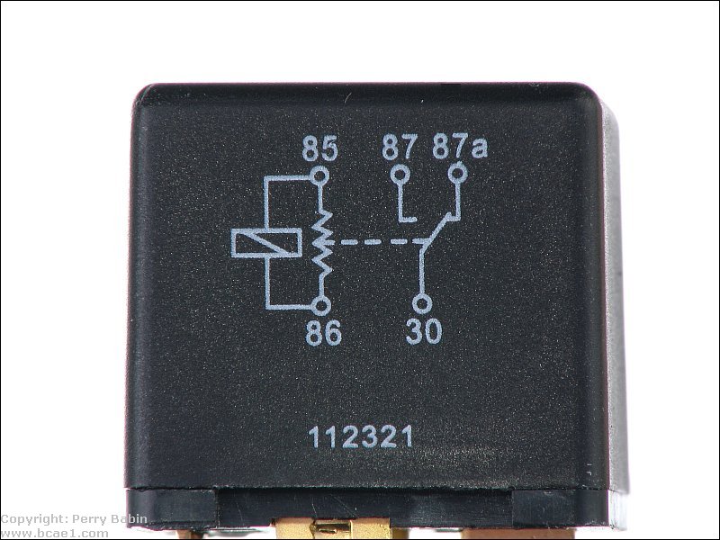
 The next image shows a relay with an internal diode supressor. The second image shows a relay with a resistor supressor. Not all relays with internal supression will have the supressor on the schematic diagram but most will.
Pull in Voltage:
Drop out Voltage:
Coil Resistance:
Remote Input Current: |
| Manufacturer | Model | Current Draw (mA) |
| MTX | 2300 | 14 |
| Jensen | LXA300 | 43 |
| Pioneer | GMX602 | 1.5 |
| Autotek | 7150 | 16 |
| Punch | 200x2 | 14-45� |
| Autotek | 200x1 | 17 |
| Coustic | Amp162� | 22 |
| Orion | 275SX | 28 |
| Crossfire | CFA1000D | 5 |
| Lanzar | Vibe 250 | 17 |
| Test conditions: 14.3vdc; Fluke model 27 DMM; The meter was inserted in the remote supply line. | ||
|
�Punch amplifiers may draw slightly more current when the power supply fuse blows. This generally causes no problem because the increase in current is still below the current normally drawn by other amplifiers.
Note:
It's been mentioned quite a few times that the Bosch relay's coil has a fairly low resistance (~75 ohms). It has also been suggested that you could use a different relay with significantly more coil resistance so that you draw less current from the remote output of the head unit. The relay below is from Radio Shack. Its stock number is 275-248. It has a coil resistance of ~400 ohms which means that it will draw ~1/5 the amount of current of the Bosch relay. In the following image, the red wire is the fused power source (10A max - even less for small wire like I've used). The blue wire is the remote from the head unit. The black wire goes to ground. The green wire goes to the remote input of the amplifiers and to fans if you have them.
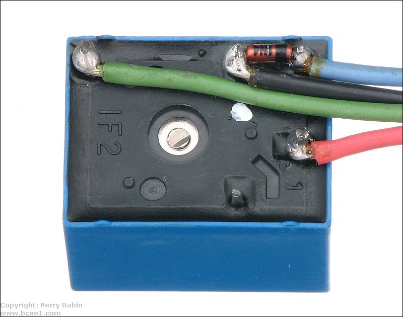
Click HERE to open this graphic in a new tab. Right-click to zoom. Left-click to drag.
TECH TIP: A relay can be wired so that it will operate when the ground connection is made/broken (instead of when the 12 volt connection is made/broken). The diagram below shows the connection. Remember that it doesn't matter which connection (power or ground) is made or broken as long as the circuit driving the relay coil is made/broken. Click the switch position selector to toggle the switch.
REASON:
Relay Terminal Connection:
REASON:
|

|

|
|

|
 Initially, relays are confusing to those new to electronics. Looking at them from the outside, they are little sealed boxes with multiple terminals. Since you generally can't see what's going on inside the relay, it can be difficult to understand how they operate. For those of you who are just starting out, just remember that, generally, they allow a very small current to control a high current circuit. It's sort of like when you start a car engine. The mechanical effort it takes to turn the ignition key is nothing compared to the effort it would take to start it with a pull rope. Essentially, the relay allows one device to effortlessly control a much larger device.