
|
| Email Home Page |
|
|
|
|
| Email Home Page |
|
|
|
A switching power supply (also known as a switch mode power supply or SMPS) pulses a DC current through the primary windings of a transformer at relatively high frequency (~20,000 - 50,000 pulses per second). This creates an alternating magnetic field around the primary winding and the core of the transformer. Since the secondary winding is also wrapped around the core and is in close proximity to the primary windings, a voltage is induced in the secondary windings. The secondary winding may or may not be electrically connected to any point of the source of the DC power. The output of the secondary is an AC voltage. In most power supplies, the AC output of the transformer is rectified by using diodes. This rectified 'DC' output voltage is commonly referred to as 'rail voltage' in amplifiers. The rail voltage is what supplies power to the output transistors in an amplifier. The output transistors drive the speakers.
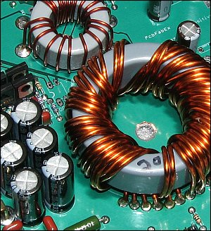
The diagram above shows a simplified version of the type of transformer that is commonly used in car audio equipment. It consists of a primary winding, a secondary winding and a toroidal core. This type of transformer is lightweight, compact and very efficient. The transformers can be much smaller than those used in home audio equipment because the operating frequency is much higher. Most home equipment simply has its power transformer connected to the AC mains supply. The mains in the US runs at 60hz (60 cycles per second). On the other side of the pond, the mains operate at 50 hz. At 50 or 60 hz, you need a much larger transformer. With a switching power supply, the engineer can pick any frequency he or she desires (after carefully considering all of the different variables).
The diagram below shows a simplified version of a switching power supply. In a typical design, Point "b" is connected to a source of power, such as the vehicle's battery. Points "a" and "c" will be alternately connected/driven to ground at a high frequency (somewhat like an electronic see-saw). MOSFET switching transistors are used to drive the transformer windings to ground in most modern amplifiers. Point "x" would be the ground for the secondary side of the transformer and can be completely isolated from the vehicle's ground. Point "y" would be the positive output rail voltage. Point Z is the negative rail voltage. The voltage on points y and z would be referenced to the secondary ground/center-tap. The diodes are used to rectify the AC output from the transformer. The capacitors are used to reduce the ripple on the output of the power supply.
 Above, it was stated that the secondary voltage (on points x and y) would be referenced to the secondary ground/center-tap. If you were measuring the voltage on the secondary side of the power supply, you would need to place the black meter probe on the secondary ground, not the primary ground. When the secondary is isolated from the primary, you will read zero volts if you place the black probe on the primary ground (the ground for the 12v supply that's supplying power to the switching power supply) when measuring the voltage on the secondary side of the power supply. If you're REALLY interested in switching power supply design for 12v systems, read the Basic Switching Power Supply Design page. |
|
You should remember: 1.The primary winding of the transformer is driven with pulsed D.C.. 2.The pulsed D.C. creates an alternating magnetic field in the core. 3.The secondary is wound around the core which causes a voltage to be induced in its windings. 4.The output of the secondary is an A.C. voltage. 5.The A.C. is rectified into pulsed D.C. through the diodes. 6.Capacitors smooth the pulsed D.C. |

|

|
|

|
 A vehicle's charging system produces less than 15 volts (not including heavy equipment and trucks). The actual charging system voltage is generally between 13.5 and 14 volts when the engine is running. This is simply not enough for many uses. For car audio, amplifiers and high output preamplifiers need more voltage. To boost the voltage, a switching power supply is typically used. The most common type of switching power supply uses a