A diode is an electronic component that, in general, will pass current in only one direction (there are a few exceptions like zener and current regulator diodes). They are used in virtually every piece of electronic equipment. In head units, they are virtually always used across the power input terminals to protect the head unit in case of reverse polarity (hooking the power wires up backwards). In amplifiers, they are used as rectifiers to convert AC to DC. In a large percentage of audio equipment, Zener diodes are used as voltage regulators. In alarm systems, rectifier diodes are commonly used to isolate 2 trigger sources.
For a general purpose rectifier diode... when the voltage on the anode is more positive than the voltage on the cathode, current will flow through the diode. If the voltage is reversed, making the cathode more positive, then current will not flow through a rectifier diode (unless the peak reverse voltage rating is exceeded).
When voltage is applied to a diode and current is flowing through the diode, there will be approximately a 0.6 volt drop across the diode. The green rectangular device is a current limiting resistor. It's needed to prevent excessive current flow through the diode when forward voltage is applied. The value indicated by the blue flags is what you would read with a multimeter if the red probe was on the point indicated and the black probe was on ground (battery's negative terminal).
----- Critically Important -----
Flash graphics viewing/use alternatives:
Flash support by most modern browsers has been dropped but that's not the end of the line for Flash.
There is no practical alternative to Flash for the interactive demos/applets/graphics on this site.. Especially when there are alternatives, some simple, some good, some...
Ruffle is chosen by most because they can't imagine using anything but their preferred browser. It works. It's OK but not great. The Flash graphics won't look as they're supposed to but it, generally, works.
The #1 preferred (by me) way to view the site and the Flash graphics is with the Chromium Portable browser and the installation of the older (no time-out) Flash Player files. This was incredibly simple when people knew computers but not today when people only know how to work with their phones.
The Flash Browser is a good option but it's so stripped down that it makes it somewhat difficult to use.
The Maxthon browsers are an option. The v4.95 is the easiest (install and use). V5.3.8 and 6.1.0 require (very) slightly more effort (very).
The Chromium and Maxthon browsers on the page above are 'portable' browsers. They are not installed into your system. They are simply made available for use on your computer. They can be carried around on a Flash drive and used on any computer.
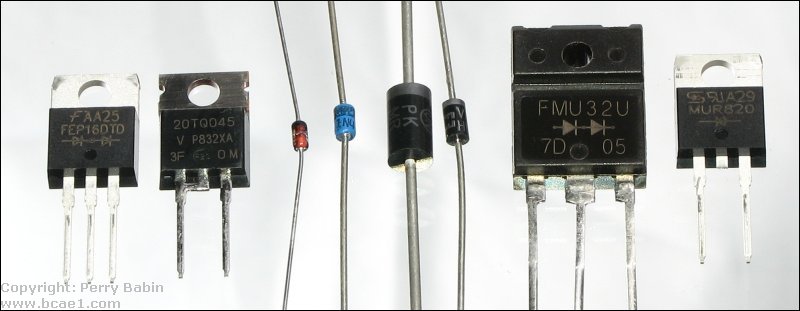
Several common diode packages. The larger packages are used as rectifiers in various power supplies, including those in car audio amplifiers. The smaller ones are typically used to block voltage or to allow voltage to flow in only one direction.
Special Purpose Diodes:
Before we discuss any specific types of special diodes, we need to show how voltage across a diode and current flow through a diode are related. The following graph shows voltage on the x-axis and current flow on the y-axis. As you can see, for a forward biased diode, as the voltage reaches ~0.6 volts the current flow starts to increase significantly. Before the voltage reaches ~0.6 volts, there is virtually no current flow. Above ~0.6v there is virtually no resistance to the flow of current. The same thing happens as the reverse voltage approaches the reverse breakdown voltage. If you push the 'sweep voltage' button, the voltage will sweep from the greatest negative value to the greatest positive voltage.
Zener Diodes:
Zener diodes are generally used for voltage regulation. The diodes are used with reverse polarity when compared to their rectifier counterparts (you hook them up backwards to make them work properly). All diodes have a point at which they will conduct current when sufficient reverse voltage is applied. Most diodes are damaged when the reverse voltage reaches the breakdown (or avalanche) voltage. This is primarily due to the lack of any current limiting resistor. Zener diode circuits have a current limiting resistor in series with the diode as part of their design. In the diagram below, you can see how the positive terminal of the battery is connected to the resistor. The other end of the resistor is connected to the cathode of the zener. The other end of the zener, the anode, is connected to ground. If the zener diode is a 5.1 volt zener, the voltage on the cathode of the zener will be very close to 5.1 volts. The voltage is going to be close (but not usually exactly) the rated zener voltage. You can sometimes get the voltage very close to its rated zener voltage by varying the value of the resistor. This changes the current flow through the diode. If you look at the curve, you can see that a change in current (near the breakdown voltage) corresponds to a small change in the breakdown voltage. This type of circuit is good for use as a voltage reference but it is not very good to supply regulated voltage to circuits that draw a large amount of current.
Diode analogy:
In the diagram below, you see a zener diode connected to a voltage source with a current limiting resistor. Just to the right of the electronic circuit, you see a rubber band (cyan) which is analogous to the resistor and a piece of nylon string (green) which is analogous to the zener diode. In the mechanical version of the resistor/zener, you see the piece of looped string and rubber band lying on the 'ground' because no voltage (force) is applied to them. When you 'apply voltage', you see a string (a 5 volt zener) being pulled up to 5 volts (inches) by the rubber band. There is no resistance to the change in voltage until the string (zener) reaches 5 volts. Any voltage between 0 and 5 volts will be unregulated and will fluctuate with the force (voltage) exerted on the rubber band. As the simulation ends, you see that the force on the rubber band is significantly more than it was when the voltage was near 5 volts. Even as one end of the rubber band is at 12 inches (volts), the piece of string (zener) is holding the bottom of the rubber band to 5 inches (volts). The rubber band (resistor) keeps from breaking the string when the voltage exceeds 5 volts (inches). If there were no rubber band and instead the force (which we will consider to be infinitely strong) moved past 5 inches (volts), the string would be instantly broken. If the resistor has insufficient resistance or the rubber band would pull up too high (higher than 12 volts/inches), the string/zener may still be destroyed.
Now for maximum confusion, what if we have a secondary load on the system. The load would act as a second rubberband pulling down on the first rubber band. A higher current load would pull down harder. To keep the regulated voltage constant, you'd have to make sure that the top rubber band could apply enough force to over come the downward force of the load and still be able to hold pull up to 5 inches (volts). If the downward force from the load was too great and the pull up resistor (rubber band) isn't stiff enough, the voltage will become unregulated. As long as the pull up resistor is stiff enough to pull up the load to 5 volts, you will have a 5 volt regulated source.
Current Boost Regulator:
The diagram below shows a circuit which will increase the available current output at a regulated voltage. The current supplied to the electronic device will pass (for the most part) through the transistor. This allows the regulator to supply current to a much tougher (lower resistance) load. Please keep in mind that you will lose approximately 0.5-0.7 volt through the transistor. If you need a regulated voltage of approximately 15 volts, you'd use a 16 volt zener. This would actually give you a regulated voltage of approximately 15.4 volts. If you need tighter/more accurate regulation, you'd have to use a more complex regulator circuit. More complex regulators are shown on the op-amp page.
Calculating Resistor Value:
For a basic voltage reference, choose a resistor that will allow about 1/4 to 1/2 of the zener's allowable current to flow.
Since Zener's are rated by the amount of power that they can dissipate and you have a 1 watt 5 volt zener diode, use the formula P=I*E.
You know that the power rating is 1 watt and the voltage is 5 volts (it's a 5 volt zener) so... with a little manipulation of the formula we have:
I=P/E
I=1/5
I=.20 amps This is the most current that the zener can safely pass.
Now bearing in mind that we are only using the zener as a reference, we will only pass enough current to make the zener function properly. About 25% of the max current should work well. 25% of .2 is .05 amps. I will assume that we're using an unregulated supply voltage of 13.5 volts (the 12 volt battery). The difference between 5 volts and 13.5 volts is 8.5 volts. The resistor will have to drop 8.5 volts at .05 amps to properly limit the current. If we use the formula E=I*R we have:
R=E/I
R=8.5/.05
R=170 ohms or the closest available value.
Then we have to find the power dissipation in the resistor. We can use the formula P=E^2/R:
P=8.5^2/170
P=72.25/170
P=.425 watts
This means that the resistor needs to have a resistance of 170 ohms and must be rated to dissipate 1/2 watt of power or more. A resistor rated at less than .425 watts will die a horrible, painful death.
These values will generally work well with the current boost regulator. If the load is taken off of the resistor/zener junction, the voltage regulation will not hold if the current draw is more than .05 amps.
All of these formulae can be found on the Ohm's Law page.
This site was started for pages/information that didn't fit well on my other sites. It includes topics from backing up computer files to small engine repair to 3D graphics software to basic information on diabetes.
This site introduces you to macro photography. Macro photography is nothing more than the photography of small objects. It can take quite a while to understand the limitations associated with this type of photography. Without help, people will struggle to get good images. Understanding what's possible and what's not possible makes the task much easier. If you need to photograph relatively small objects (6" in height/width down to a few thousandths of an inch), this site will help.
If you're interested in air rifles, this site will introduce you to the types of rifles available and many of the things you'll need to know to shoot accurately. It also touches on field target competition. There are links to some of the better sites and forums as well as a collection of interactive demos.
This site helps anyone new to computers and anyone with a basic understanding of computers with a desire to learn more about the internal components of a computer. If you have a computer that you'd like to upgrade but don't know where to start, this is a good site for you.
This site is for those who want to begin racing karts but don't fully understand how the various parts work. It's mostly interactive demos that show how the various parts of the kart work.
You should remember:
1.Current will only flow in one direction through a diode.
2.When current does flow through a diode, the voltage on the anode will be approximately 0.6 volts higher than the voltage on the cathode.
Click HERE to visit a friend's new car audio tech site.


 A diode is an electronic component that, in general, will pass current in only one direction (there are a few exceptions like zener and current regulator diodes). They are used in virtually every piece of electronic equipment. In head units, they are virtually always used across the power input terminals to protect the head unit in case of reverse polarity (hooking the power wires up backwards). In amplifiers, they are used as rectifiers to convert AC to DC. In a large percentage of audio equipment, Zener diodes are used as voltage regulators. In alarm systems, rectifier diodes are commonly used to isolate 2 trigger sources.
