Although many people are now using cool-running class D amplifiers to power the subs in their vehicles, those amps and the class AB or class B amps that they're using for mids and highs can generally benefit from forced air cooling. It's obvious with class AB or class B amplifiers because the heatsinks get so hot but not all of the heat in all amplifiers is transmitted to the heatsink. Many of the class D amplifiers have circuitry that operates at such high temperatures that the electrical components actually damage the circuit board over time. Even those with internal fans (fans that do not pull fresh air into the amp) are only moving around hot air and getting a bit of cool air into the amp can make the amp more reliable. Generally, you want to force cool air through the fins of the heatsink. This will most efficiently cool the amp. If the fins run the length of the heatsink and there are vents on the end of the heatsink, use a fan to force air into those vents and through the fins on the heatsink. This is the image from the Modded P45' page of the site where this was initially recommended.
Click HERE to open this graphic in a new tab. Right-click to zoom. Left-click to drag.
There have been a lot of people who have cut holes in the bottoms of their amplifiers to install fans and this may help a bit (maybe more than a bit for class D amps), it does very little for class AB and class B amps. Just about the only time that this is useful is when an amp is being abused by running it below its rated load AND there is a fan blowing through the fins of the amp.
If you're building your amps into an amp rack, you need to make sure that the fans in the amp rack work with and not against the fans in the amp. If the fans in the amp are blowing against the ones in the rack, it can actually reduce the air flowing through the amp and make things worse.
Fan Specifications and Miscellaneous
Brushless Fans:
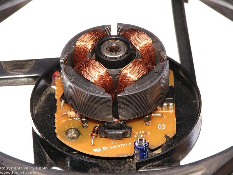
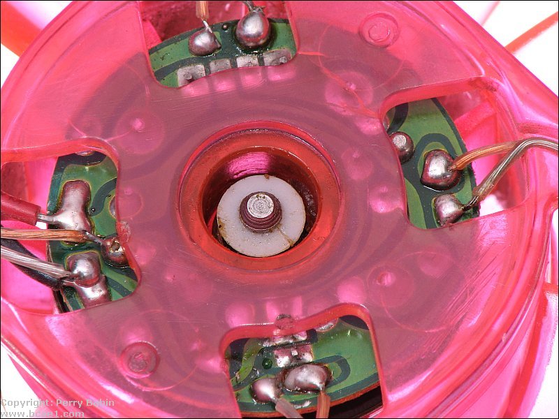
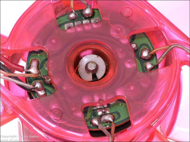
Most of the fans used in car audio are 'brushless' fans. Old type fans had brushes that were used to make contact with a moving commutator. This worked well enough for most applications but they produced a lot of electrical noise which could find its way into the audio signal line. In a fan that uses brushes, the voltage is applied to ever-changing windings as the armature rotates. In a brushless motor, there is no electrical contact with the spinning rotor. There are coils on the frame of the fan motor and a ring of magnets inside the fan's hub. The ring of magnets has alternating magnetic fields. There is a 'hall sensor' on the board that tells the control IC when a particular magnetic field is present and the control IC drive the coils on which pulls the rotor around. In the image below, you can see the coils, the control IC and the hall sensor (H1).
Current Draw:
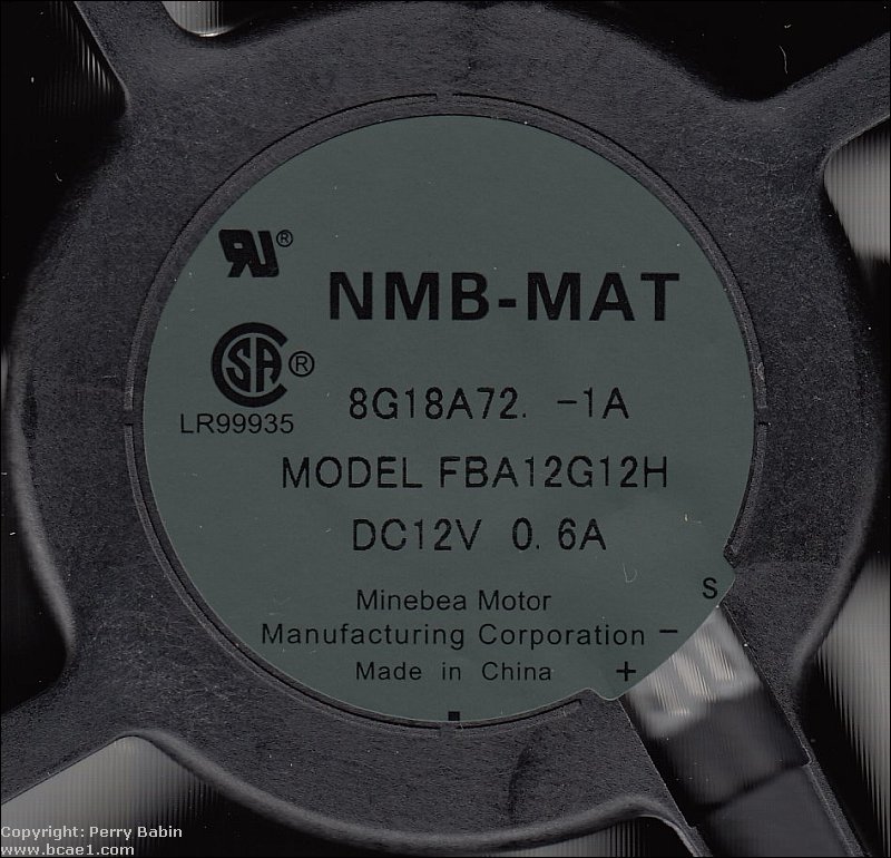
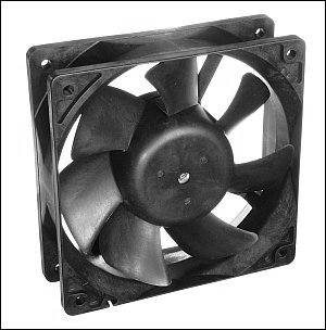
Although a brushless fan generally draws very little current (about 3 amps is the most you'll see for a 120mm fan), it's important to be aware of the current draw. The following is the label for the fan at the top of the page. As you can see, the rated voltage is 12v and the rated current draw is 0.6 amps. Compared to the current draw of amplifiers and other components, this is insignificant but as you can see, it's much more than you'd want to draw from your head unit's remote turn-on lead. That's why you almost always use a relay to drive the fan (and other accessories).
Bearings vs Bushings:
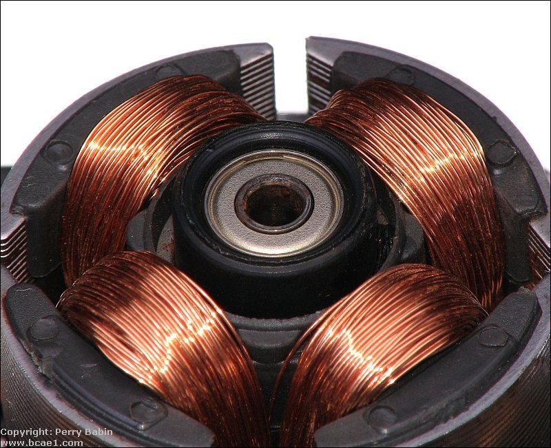
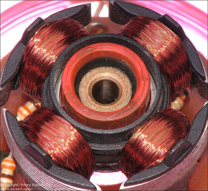
When you buy a fan, you may look for the lowest price but that's rarely going to get you the highest quality fan. Fans can be purchased with bushings (also known as sleeve bearings), one ball bearing and one bushing and with two ball bearings. If you want a fan that will work for years to come, all else being equal, the fan with two bearings will operate the longest without any maintenance. The fan below has sealed ball bearings (sealed to retain lubricant and keep out contaminants). The second image below shows the brass bushing of a cheaper fan.
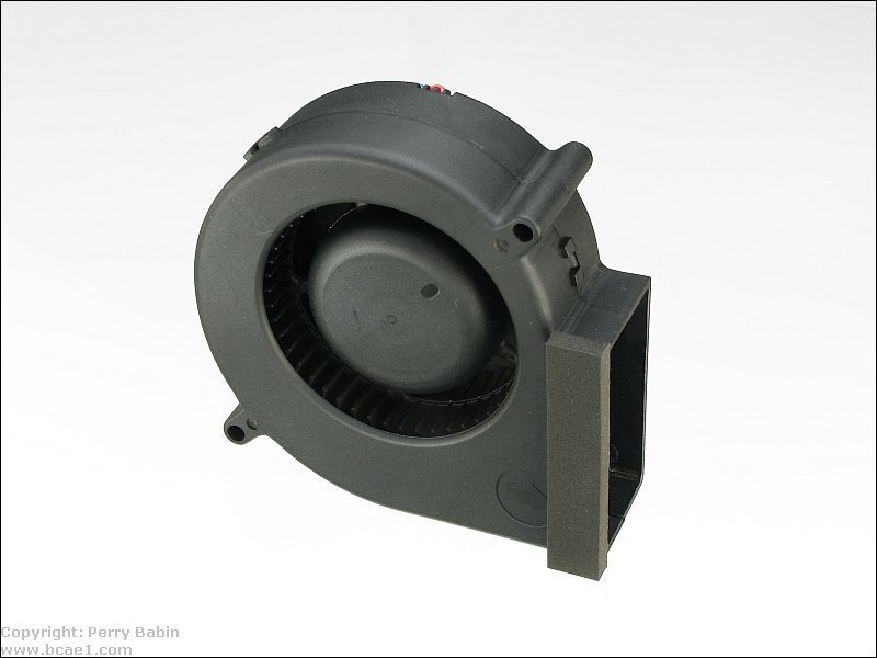
Squirrel Cage Fans:
The fan below is referred to as a blower, a squirrel cage fan and a centrifugal fan. This fan uses centrifugal force to move air. The air enters the round port and is forced out of the rectangular port. For their size, these fans can move a lot of air. There is a lot of discussion as to whether to call these blowers or fans. The distinction is often the ability to move air against a resistance. Fans can build very little static pressure. Blowers can build significantly more static pressure. You can tell the difference by placing your hand in front of a running fan. When you get close to a propellor type fan (one with regular blades), the air flow diminishes significantly. If you do this with a squirrel cage fan, the air flow will remain largely un-changed until you almost completely close off the output port. These can be used in place of standard fans in amp racks or for virtually any application where you need to move air. If you search for these on eBay, you should search for blower instead of squirrel cage fan. 12 volt blower seems to produce the best results.
CFM:
The fan's output is rated in CFMs (Cubic Feet per Minute). Higher CFM fans move more air but they are also generally noisier so there is a tradeoff. You have to determine which is more important, air flow or a low noise level.
Noise Level:
The noise level is generally rated in either dB or sones. The dB ratings will generally have a specific reference like dBA (A-weighted which is the easiest weighting to get a low rating). THIS is the datasheet for a very high velocity (190CFM) fan. It's rated at 59dB. That's going to be a loud fan and probably not useful where the user will be in close proximity (like in a computer case). The fan used at the top of this page is an FBA12G12H1A. It's rated at about 100CFM and is relatively noisy but virtually all of the noise is from the air flowing through it. Most 120mm fans are rated at 50-80CFM.
Lubricating the Fan
Most fans with bushings are relatively easy to repair (lubricate). Most have a split-ring retainer under the label. Sometimes it's covered by an oil seal (which just pops out). Below, you can see the split-ring as it normally is and after it's been part-way removed. To clean and lube the bushing, remove the ring completely and push the shaft for the rotor out of the bushing. The magnets will fight you a bit but it will pop out if you push it far enough. Keep track of all of the o-rings. Clean the shaft and the inside of the bushing with acetone. Use a cotton swab with most of the cotton removed to clean the inside of the bushing. For smaller fans, you'll have to remove the cotton and several layers of paper to allow it to fit in the bushing. When it's clean, use a moderately heavy oil (similar to 30 weight motor oil) or a very light grease (lithium based white greases are generally suitable). Smaller fans need lighter lubricant that the larger fans so that the fan can turn freely. The larger motors have enough torque to overcome the damping by the heavier grease.
Current Flow and Safety
The following diagram shows the relay controlled by a switched 12 volt source. It shows a fan and a neon tube (it could be virtually any 12 volt device) being supplied power from terminal 30 of the relay. The power source is the battery/charging system. To have a safe system, we have a fuse at the battery. With a Bosch relay, you can use any fuse up to a 30 amp fuse (the relay is rated for 30 amps). The required size of wire segments A, B and C is determined by the size of the fuse (and the current demand from the electrical accessories). If the total required current draw will be only about 10 amps, you could use a 16g wire and fuse 'A' would need to be a 10 amp fuse. If the total current draw was going to be 25-30 amps, you'd need at least a 12g wire and a 30 amp fuse. The rating of fuse 'B' is determined by the current draw of the fan and the wire connecting the fuse to the fan. If the fan draws no more than 5 amps (very likely), you could use a 5 amp fuse and a 16g wire (16g is the minimum size I'd recommend using because when you use anything smaller, it's difficult to get good, reliable connections). The size of fuse 'C' and wire 'E' are determined by the current draw of the neon. Fuses 'B' and 'C' should be as close to the relay as possible.
----- Critically Important -----
Flash graphics viewing/use alternatives:
Flash support by most modern browsers has been dropped but that's not the end of the line for Flash.
There is no practical alternative to Flash for the interactive demos/applets/graphics on this site.. Especially when there are alternatives, some simple, some good, some...
Ruffle is chosen by most because they can't imagine using anything but their preferred browser. It works. It's OK but not great. The Flash graphics won't look as they're supposed to but it, generally, works.
The #1 preferred (by me) way to view the site and the Flash graphics is with the Chromium Portable browser and the installation of the older (no time-out) Flash Player files. This was incredibly simple when people knew computers but not today when people only know how to work with their phones.
The Flash Browser is a good option but it's so stripped down that it makes it somewhat difficult to use.
The Maxthon browsers are an option. The v4.95 is the easiest (install and use). V5.3.8 and 6.1.0 require (very) slightly more effort (very).
The Chromium and Maxthon browsers on the page above are 'portable' browsers. They are not installed into your system. They are simply made available for use on your computer. They can be carried around on a Flash drive and used on any computer.
----- Critically Important -----
Click HERE to open this graphic in a new tab. Right-click to zoom. Left-click to drag.
The main points to remember are...
The wire supplying power to the relay must be protected by a fuse and the fuse must be rated to open before the wire overheats and converts your vehicle into a raging inferno.
If there's a single wire carrying the current away from the relay to a fused distribution point (like wire 'C'), it must be the same size (or larger) as the main supply wire.
The fuses going to the individual electrical accessories must be rated to protect the wires supplying the current to the device(s).
If the wire feeding the individual accessories is the same as the main supply wire, the main fuse (near the power source) will protect all of the wires.
If you want your cooling fans to operate only when your amplifiers are on, it will be necessary for them to be powered only when the remote output lead has 12 volts on it (when your head unit is powered up). I would NOT recommend powering them directly from the remote power lead. It would probably be damaged by the current draw of the fans. The diagram below is a connection diagram that may be used to supply power to the fan(s). If you have multiple amplifiers and signal processors, the output from terminal 30 can also be used to supply power to the remote terminals of those devices.
Click HERE to open this graphic in a new tab. Right-click to zoom. Left-click to drag.
If you only want the fans to come on above a specific temperature, you can use a thermistor. Since you won't be designing a circuit for mass production, you want something that is fairly flexible and can produce the desired results without a lot of testing. The diagram below is a circuit which uses an op amp as a comparator with an output which goes high when pin 5 goes higher than pin 6. I decided to use a thermistor with an op-amp to prevent the self heating that you get when you try to drive a relay coil with the thermistor. Both methods work but unless you know which thermistor you need for a particular relay, you'll have to use trial and error to find the right part.
In the following demo, you can change the temperature and voltage on the potentiometer. To change the voltage on the potentiometer, click above or below the arrow (on the right side of the potentiometer). This controls the reference voltage on the negative input of the op amp. Setting it lower makes the fan come on at cooler temperatures. To change the relative temperature, click on the thermometer. The value above the thermometer is an approximation of the thermistor's resistance. When the conditions are right, the relay will engage and the fan will run. Click HERE to make the demo fill this window.
When initially setting up this circuit you need to adjust the voltage at pin 6 to 1/2 of the voltage on pin 8. This will cause the fan to switch on at approximately 150F. You can set it lower if you want the fan to come on earlier.
If you want to use an FET to control the fan, the diagram below shows you how to connect the FET to the op amp. Keep in mind that you must insulate the tab of the FET. If the tab of the FET touches to ground, the fan will run. As an alternate FET, you can use an IRFIZ44. It's a fully insulated part and won't require an insulator. If the fan draws more than ~1/2 amp, the FET might benefit from a small heat sink.
If you need more info on the circuits above, E-mail me and I'll try to help.
Possible supplier: Mouser electronics http://www.mouser.com
Parts list:
Thermistor: 334-4227-503
Potentiometer: 531-PT10V-100k (not critical)
Op amp: 511-LM358N (critical)
FET: 570-IRF540 or IRFIZ44 or IRFZ44
Bipolar transistor: 625-MPSA06 (or equal)
Resistors: None are critical and can
likely be purchased at Radio Shack.
This site was started for pages/information that didn't fit well on my other sites. It includes topics from backing up computer files to small engine repair to 3D graphics software to basic information on diabetes.
This site introduces you to macro photography. Macro photography is nothing more than the photography of small objects. It can take quite a while to understand the limitations associated with this type of photography. Without help, people will struggle to get good images. Understanding what's possible and what's not possible makes the task much easier. If you need to photograph relatively small objects (6" in height/width down to a few thousandths of an inch), this site will help.
If you're interested in air rifles, this site will introduce you to the types of rifles available and many of the things you'll need to know to shoot accurately. It also touches on field target competition. There are links to some of the better sites and forums as well as a collection of interactive demos.
This site helps anyone new to computers and anyone with a basic understanding of computers with a desire to learn more about the internal components of a computer. If you have a computer that you'd like to upgrade but don't know where to start, this is a good site for you.
This site is for those who want to begin racing karts but don't fully understand how the various parts work. It's mostly interactive demos that show how the various parts of the kart work.
You should remember:
1.A cooler amplifier will last longer and will be less likely to fail.
Click HERE to visit a friend's new car audio tech site.


 Although many people are now using cool-running class D amplifiers to power the subs in their vehicles, those amps and the class AB or class B amps that they're using for mids and highs can generally benefit from forced air cooling. It's obvious with class AB or class B amplifiers because the heatsinks get so hot but not all of the heat in all amplifiers is transmitted to the heatsink. Many of the class D amplifiers have circuitry that operates at such high temperatures that the electrical components actually damage the circuit board over time. Even those with internal fans (fans that do not pull fresh air into the amp) are only moving around hot air and getting a bit of cool air into the amp can make the amp more reliable. Generally, you want to force cool air through the fins of the heatsink. This will most efficiently cool the amp. If the fins run the length of the heatsink and there are vents on the end of the heatsink, use a fan to force air into those vents and through the fins on the heatsink. This is the image from the Modded P45' page of the site where this was initially recommended.