The term head unit in a car stereo system used to refer to a 'tape deck' or a CD player but nowadays, it's as likely to be an MP3 player, a cell phone capable of MP3 playback or even a tablet computer. The conventional CD player type head unit often has a built in amplifier that can drive speakers directly. The average MP3 player, cell phone or tablet computer (if used without a conventional head unit) will have to drive an amplifier which will drive the speakers. Although the MP3 player, cell phone and tablet computer can drive an amplifier directly (via the headphone jack), they are often connected to the amplifier through a conventional head unit with auxiliary (aux) inputs, dedicated iPhone type inputs, USB data inputs or via a wireless Bluetooth connection.
A quick note about OEM head units...
If you're thinking about replacing an OEM head unit, you should do some research. Forums for the type of vehicle you have are generally a good place to start. Some vehicles use the OEM head unit for various functions (chimes, warnings, On-Star...). Generally, most of the OEM functionality can be retained but doing so adds $200 or more to the installation (kits, interfaces, labor...). If you are going to have the new head unit installed instead of doing it yourself, knowing what your vehicle will need will allow you to be a bit more confident that the salesman isn't trying to rip you off.
Digital Media Receivers:
In the past, CDs were the media of choice but that's no longer true. Nowadays, almost everyone opts for digital media (generally via a USB device, iPod, USB flash drive...). Manufacturers of head units now offer head units without CD players. For a lot of people, this is a good choice. There's no point in paying for a CD player that you won't use. Digital media receivers can be purchased for well under $100. Most of the ones at or near $100 have built-in 4 channel amplifiers, 4 preamp outputs, multi-band equalizers, wireless remote controls and options for satellite or HD radio.
Power Connections:
Most head units have 2 power input connections that have to be connected to a 12 volt source. The 'battery' or 'memory' wire has to be connected to a constant source of power (has power on it at all times - even when the ignition switch is in the off position). The other power wire (the 'ignition' wire) is connected to a power source that's controlled by the ignition switch and therefore will only have power on it when the ignition switch is in the 'on' or 'acc' position. Most of the wires on head units use standardized color codes for most of the wires. Wires for special features may not adhere to any standard color codes so if the wires aren't tagged or otherwise marked, you may have to refer to the owner's manual.
The following diagram shows some of the wires that are commonly found on aftermarket head units.
Speaker Level Outputs:
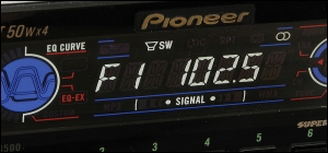
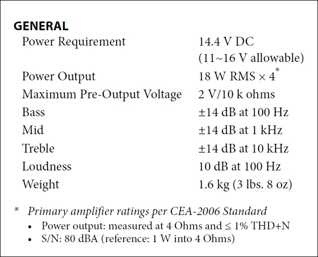
Most head units have speaker level outputs that are designed to drive 4 speakers. The power output from a high power head unit is generally limited by the voltage available which is generally no more than 14v DC. This limits the RMS power output to about 20 watts per channel (one 4 ohm speaker per channel). In general, the manufacturers that state that their head units can produce 30 or more watts of real power into 4 ohms are misleading you or are outright lying. There are a few head units using ICs capable of producing a bit more power because the IC has the ability to boost the supply voltage but those are rare. When looking at the power ratings, only consider the ratings that are CEA-2006 compliant. As an example, the following is from the owner's manual for an Alpine CDE-136BT. On the Alpine web site, it states that the 'MAX' power is 50x4 and if that's all that they would give for power ratings, that would be misleading. If you read all of the specifications, you can see that the CEA-2006 compliant rating is 18x4 at 14.4v DC.
Note:
On "high power" units, the internal audio amplifier will be instantly damaged if a speaker output wire is allowed to contact anything except a speaker terminal, even if the volume is set to zero. The damage will be severe enough that the head unit will have to be serviced before it can be used. Repair cost is often more than $100 which makes many of the budget head units uneconomical to repair. Be sure that there is no power to the unit when making any connections. This link explains why the outputs will be damaged if they contact ground.
When installing speakers in the doors of your vehicle, you must make sure that the terminals cannot make contact with the door. This will ground the speaker level outputs from the head unit and the head unit will be damaged. When inserting the speaker into the door, look at the point where the speaker terminals will be when the speaker is installed and screwed down. If possible, reach behind the speaker and confirm that there is clearance around the terminals. Also make sure that the speaker, it's terminals and the wiring is well clear of the window and the parts that move when the window is lowered. This is important because head units are often damaged when people don't think about all possible scenarios.
When a head unit's internal amplifier fails, it will sometimes cause the head unit to blow fuses. If a fuse larger than the recommended fuse is used, it will sometimes blow the leads on the internal amplifier IC and sometimes it will cause extensive damage to the head unit so you should not try a larger fuse. There's no reason that a fuse that's worked perfectly for days/months/years suddenly needs to be larger unless there is a serious problem. For the times when the internal amp fails but doesn't cause the fuse to blow, it will obviously cause the speaker level outputs to quit working but in some head units, Pioneer most commonly, it will cause the remote turn-on to stop producing output. If this happens, you can connect the remote that goes to the amplifiers to the red wire of the head unit. This works relatively well but sometimes causes a pop if the head unit is switched on or off (with the power button on the head unit) while the ignition switch is in the acc or on position.
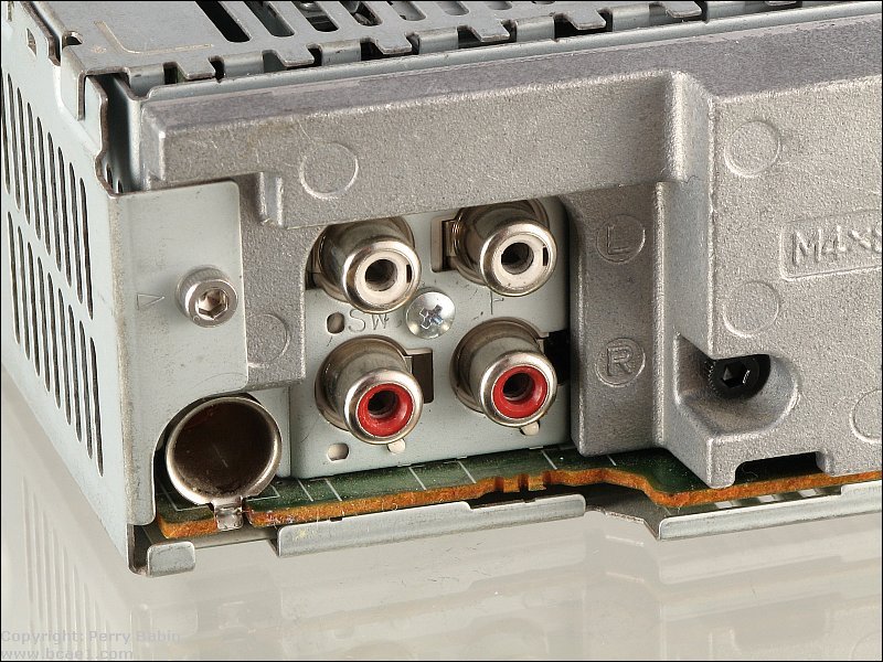
Preamp Outputs:
Preamp level outputs are audio outputs that are used to drive an amplifier (or equalizer or crossover...). Preamp level outputs do not have enough output current to allow them to drive speakers directly. They are generally included on higher end equipment. In virtually all cases, they will have RCA type connectors. Some units will have only one set of preamp outputs (would likely be a 'rear' output). Other units have multiple pairs of outputs for front, rear and subwoofer signals. Some head units allow you to switch a low pass crossover on for the rear outputs to convert them to a subwoofer output.
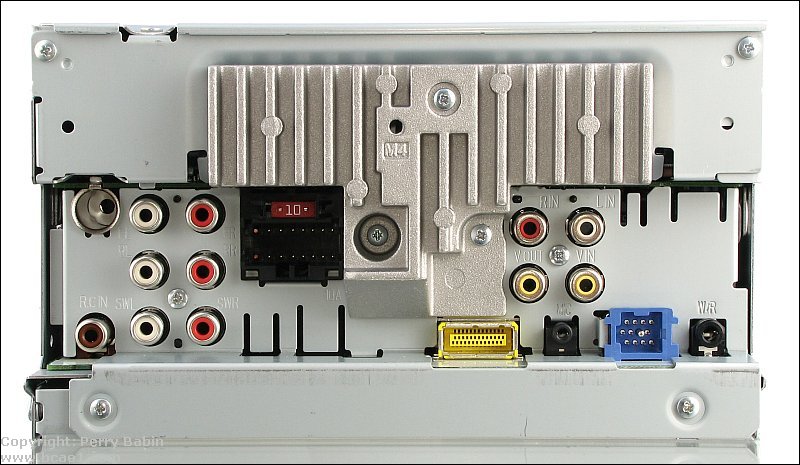
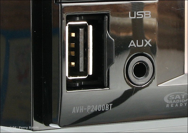
The following head unit has a few more features than the previous model. This is a mid-range Pioneer head unit (AVH-P2400BT). This one has dedicated front/rear/sub outputs. As you can see, it has other connectors. These will be covered in upcoming sections.
RCA Cables and the Shield Ground:
Do not allow any source of power (12 volts) to come in contact with the shield (outside metal part) of the RCA cables. The shield is grounded to the case of the head unit. It is the reference for the preamp audio signal. If it comes in contact with a source of power, the ground connection inside the head unit will be damaged. This can cause lots of problems including blown tweeters, engine noise, lack of bass... Pioneer head units are particularly susceptible to this because Pioneer uses a shield ground fuse. The fuse helps protect the vehicle from an electrical fire. People condemn Pioneer for this but Pioneer has actually done many of them a favor by preventing an electrical fire. If this does happen, you can temporarily restore the ground connection with a fused jumper. Details can be found on THIS page.
Other Inputs and Outputs:
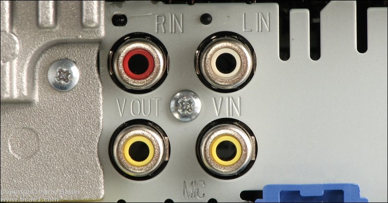
In the next two photos, you can see several video jacks. On the right, there are three jacks (two for audio and one for video). These are for a multimedia source. The video output is used for rear-passenger video monitors. The video is disabled on the head unit when the parking brake is not on (except when the transmission is in reverse).
The jack on the left is the rear-view camera input. This input is enabled when the vehicle is in reverse.
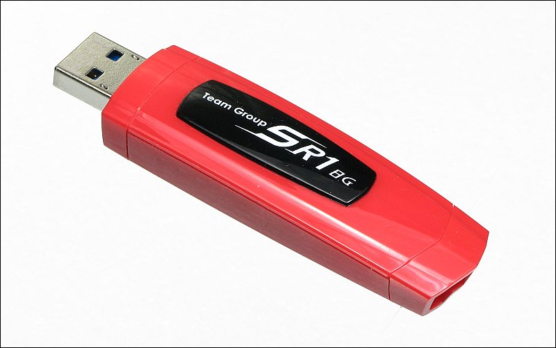
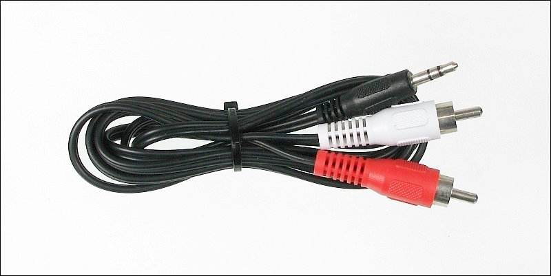
Even some of the bottom-of-the-line head units have multiple input choices. The most common are the USB and the 1/8" mini/RCA input. The USB input can accept USB flash drives (and other drives with USB connectivity). Generally, the USB device plugs directly into the front of the head unit. The analog 1/8" mini/RCA input can be on the front (1/8") or back of the head unit. The analog input will be driven by the headphone output of the audio device. Some head units have a dedicated iPod or iPhone input that requires a special cable. Those are being phased out. The newer head units use the sync/charging cable and the USB interface.
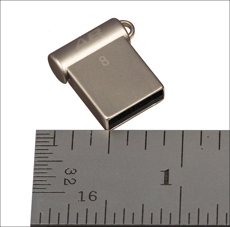
This is the front panel USB and 1/8" input ports on the Pioneer 2400BT. When you have a USB flash drive plugged into the front panel, it is easy to damage the drive or the head unit if it's accidentally hit. Small drives that barely stick out from the panel (like THIS) are available. If you have a really large capacity drive that you want to use, it may be a bit less susceptible if you use a short USB extension cable. It won't stick out as far and is a bit more flexible so if it's hit, it's less likely to damage the USB port on the head unit.
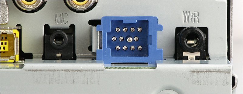
There are other inputs on this head unit that you may not see on lower models. In the following photo, the 'MIC' jack serves double-duty. For normal operation, it serves as the mic input for phone calls. For setting up the head unit, a special microphone is used to set the equalization. The center (blue) connector is the IP-BUS jack. This is used for the HD radio tuner and the Bluetooth adapter (for the model below this that doesn't have built-in Bluetooth capability). The black jack on the right is for a wired remote. This can be used in several ways. For marine applications, there is a weather-proof wired remote that can be mounted in the open, leaving the head unit protected from the elements. For automotive applications, you can use an interface like the PAC SWI-PS to retain the use of your steering wheel controls.
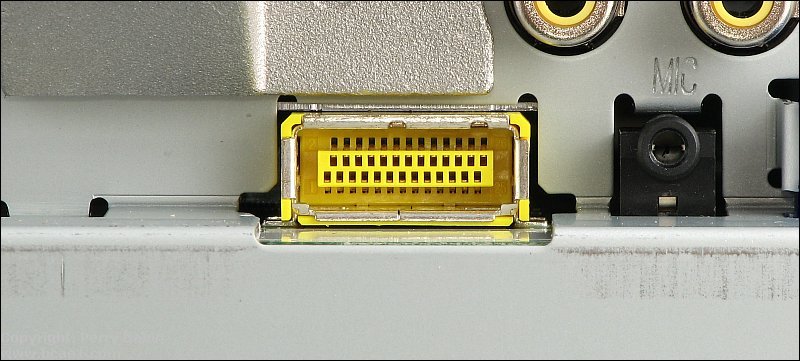
The yellow connector in the following image is for the navigation module. Some head units have navigation built-in. Others (like this one) are nav-capable and require an external module.
Broadcast Media
Just a few years ago, the only types of broadcast media for car audio were AM and FM broadcasts. Now there are other options.
Satellite Radio:
Satellite radio is delivered via satellite. It requires a special receiver. The receivers are built into some head units but are generally optional and require a separate module. SiriusXM is the best known satellite radio provider at this time. The content varies by station and can be virtually anything (music, sports, comedy...). Unlike other broadcast radio, it's uncensored so all content may not be suitable for all family members. SiriusXM is a pay service that costs $10-15/month. Unlike other pay services like Pandora or Rhapsody, there are some commercials on some channels.
HD Radio:
HD radio is a parallel broadcast with content that mirrors the content of the normal broadcast for the radio station. HD radio is free (if your head unit has a built in HD tuner) so there are no subscription fees.
Both HD and satellite radio can provide CD quality sound but the sound quality will depend on the content provider. In the case of HD radio, the difference in sound quality between the normal broadcast the HD broadcast may be minimal, especially if you have a good tuner and good reception in your area.
Remote or Power Antenna Output:
There may be one or more switched 12 volt outputs on your head unit. These outputs are usually called remote outputs. They are used to control power amplifiers or power antennas. If your unit has only one remote output, 12 volts will be sent through it when any audio source is being used (tuner, CD, tape, aux...). It will be 'hot' (have 12 volts on it) when the head unit is on. It will have no voltage when the head unit is off.
If the unit has two remote turn-on wires. One dark blue wire will be for your power antenna and will only have 12 volts on it when you are using the tuner. It will have no voltage on it when the head unit is switched to CD, aux or is switched off. This is so that your power antenna will go down when it is not needed. The second output (generally a dark blue wire* with a white stripe for aftermarket radios) will be marked amp remote (or amp turn-on) and will have 12 volts switched to it when any source is in use. There is a diagram on the Test Light page that shows both types of outputs.
Please note that the remote wires for stock (OEM) radios will be of a different color (probably not blue). You can refer to the following page for the color code for your vehicle. the12volt.com
*At one time, there was no standardization for the power antenna/amp control wires. Some used the blue/white for power antenna. Others used the solid blue for the power antenna. Now, it's fairly standard to have the blue for the power antenna control wire (loses 12v when the tuner isn't being used) and a blue/white for the amp control. If there is only one output, it's likely to be blue/white.
Fuses:
Most remote outputs are switched through a very small transistor or the fragile output of an expensive IC. This means that they are EASILY damaged by excessive current flow. The remote output lines should be fused close to the head unit with a .5 amp fuse. A 1 amp fuse may not protect the switching transistor (the one that supplies power to the remote output). Do not try to use the remote output to power fans directly. If you want to do anything more than turn on amplifiers, you need to use a relay as a buffer.
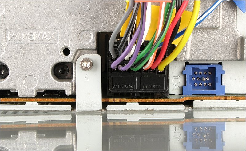
In some head units, the fuses are not always in plain sight. In the case of some Pioneer head units, the fuse is hidden under a tab on the plug for the wiring harness. In other harnesses, the fuses are in black boxes inline with the wires in the harness. The owner's manual for the head unit will show you where the fuses are. These can often be downloaded from the manufacturer. The Crutchfield site also generally has the owner's manuals available for download for head units that they sell or have sold. For older models, Google Crutchfield and the model of the head unit. They won't generally come up through the site's search engine.
Be Careful with the Wiring Harness:
Don't treat the wiring harness like it can be replaced easily or inexpensively. The wiring harness for many head units can cost more than $50 and some are no longer available. It's important that you not pull on any individual wire too hard. If you pull it out of the plastic plug, it's likely to shear off the locking tabs which will make it difficult to keep it in the plug. This will, at the very least, be annoying. It could make the head unit un-usable. Don't cut the wires too short. If/when the wires get to 6" or less, add more wire on and for future installations, cut the wire that has been added. This is especially important for harnesses that have inline fuses.
Stock/Factory/OEM Head Units:
If you have a stock head unit and don't want to replace it, you'll likely need to use a Line Output Converter (LOC). It will convert the speaker level signal to a preamp level signal. Many times, the LOC is connected to the speaker wires that feed the speakers in the rear deck (parcel shelf) of the vehicle (especially when the LOC is going to be used to drive an amplifier which is going to drive a subwoofer). If the system is going to use multiple aftermarket amplifiers for front/rear and subs, you'll use 2 LOCs and they'll be installed behind the head unit. If your head unit doesn't have a built in amplifier (it would have amplifiers elsewhere in the vehicle), you'll have to connect the LOCs to speaker wires (after the amplifiers) wherever you can get to them. For vehicles with special 'systems' like the Bose system, you may need a special adapter. PAC makes both LOCs and system-specific adapters.
Speaker Output Clipping:
If you use an LOC, you will have to set the gains on your amplifier so that the amplifier reaches full power before your head unit's volume control reaches 1/2 volume. Most radios' speaker outputs will start to clip at about 1/2 volume (especially if the bass is boosted by the head unit's equalization or tone controls). This is far earlier than the point where the preamp output signal starts to clip on most radios. The only time that I've seen a preamp out start to clip along with the speaker output is when the preamp output signal is derived from the speaker output via a voltage divider network (sort of a cheap internal LOC). This was usually only done on the bottom_of_the_line head units in the past and is rarely seen in newer head units.
If you blow a fuse when installing your head unit, consult your owner's manual for the proper replacement fuse size. By proper size I don't mean physical size. I mean amp rating. If an electronics manufacturer specifies a certain size fuse, they do it for a good reason. They know what the equipment and internal electronic devices can handle. More than half of the head units that I serviced would not have been damaged if the proper fuse would have been used.
TECH TIP
Unused Speaker Wires On Head Unit:
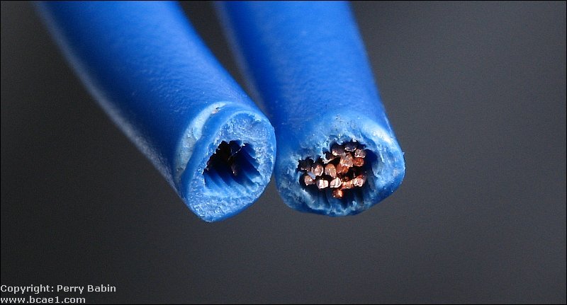
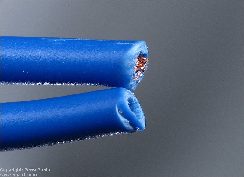
If you are not using your speaker output wires, cut them off so that there are no copper strands sticking out of the insulation AND tape up or otherwise insulate the end of the wire. You may be able to pull on the insulation so that it stretches over the end of the cut off copper wire. If the speaker wires on a high powered radio are allowed to touch to any grounded piece of metal, the head unit's internal amplifier will be instantly damaged (this was mentioned previously but bears repeating). The following two images show one that's simply been cut and one that had the insulation pulled after cutting. You can clearly see that there is less of a risk of the one that was pulled shorting to anything else.
Aftermarket Wiring Harnesses:
When installing an aftermarket head unit, you should not cut the factory plug from the vehicle's factory wiring harness. Instead, you should buy an aftermarket wiring harness that would plug into the factory harness. These harnesses (such as those made by Metra) will have each wire marked with it's function (ignition, battery/constant, speakers...).
You would connect the harness to your radio with butt connectors (or other connectors) and then simply plug the harness into the factory harness. If you want to reinstall your factory head unit at a later date, you'd be able to plug it right back into the factory harness.
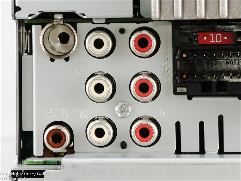
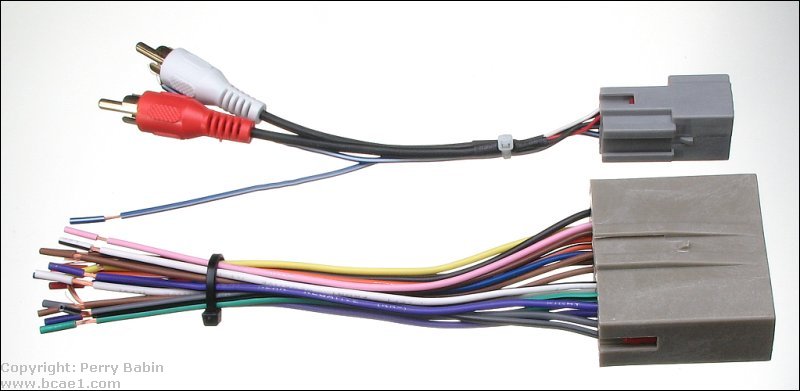
Aftermarket Wiring Harness:
Not all head units can produce preamp level output but for those that do, the adapter is often included with the harness.
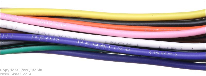
Close-up of markings:
Head Unit Opening Size:
Most OEM head units and the openings in the dashboard of most vehicles are DIN compliant. The DIN standard specifies that a 'single DIN' radio opening is 180mm x 50mm (approximately 7" x 2"). Larger openings are either 1.5 DIN (DIN and a half) or double DIN (180mm x 100mm). Although it's sometimes possible to mount a larger head unit in place of the OEM head unit, it's not always easy unless there is a 'pocket' above or below the head unit. When there are ventilation controls or display units above and/or below the head unit, mounting a larger head unit requires the relocation of those components which can be very difficult and very time consuming. For those who want a large (approximately 7") display on their head unit but only have a single DIN slot, motorized displays are available. These slide out of the single DIN head unit and flip up to be viewed. For anyone buying one of these, I'd STRONGLY suggest buying an extended warranty and only buying one from one of the manufacturers that sell replacement parts (Pioneer, Alpine, Sony, Kenwood). The other option is to buy one that's so inexpensive that you simply replace it when it breaks (and they break quite often).
Increasing the Useful Service Life of Your Head Unit:
There are a few things that you can do to help extend the life of your head unit. One of the most common failures of head units is worn out tact switches (the switches that click when you press the buttons). To extend the life of these, there are two things that you can do. First, don't unnecessarily, repeatedly press the buttons. Many people do this for volume or to go through the radio station presets. If you wear out one of the buttons and it sticks in the 'down' position, it can cause the rest of the buttons to be inoperative. The microcontroller can accept only one command at a time and if a switch is stuck in the down position, it locks out the rest of the buttons. The rotary encoders used for the volume controls on head units that have volume controls that spin more than 360� are also switches and can wear out. More use makes them wear out more quickly. Many people consider a remote control for a car audio head unit to be useless or only for those too lazy to reach for the head unit but using the remote saves the switches and the appearance of the head unit. You can replace most remote controls for less than $50 which is far less than repairing the switches in the face of a head unit.
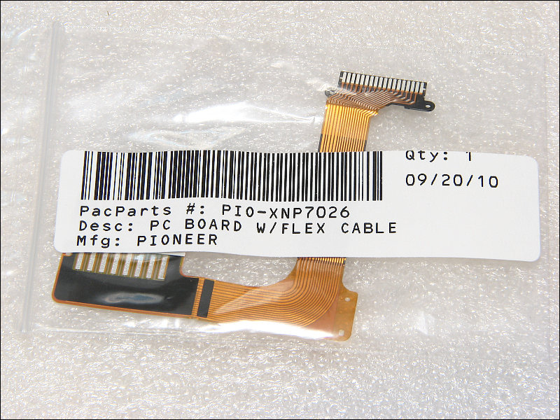
If you have a head unit that has a motorized or flip-down face (also applies to some head units that have a face that flips-down to allow access to the CD player loading slot), it almost certainly uses ribbon cables to connect the face to the main board. These wear out. If you constantly open and close the face or the face opens and closes (or moves in any way) every time you power up the head unit, 'expect' the ribbon to fail. Moving the face less often will increase the life of the ribbon. When the ribbon begins to fail, the functions of some of the buttons or some other aspect of the face's operation will become intermittent and the head unit will eventually become inoperative. You can generally buy the ribbon cables for about $20. PacParts.com has the most common ribbon cables. If you have to have it replaced by a repair shop, expect to pay about $100.
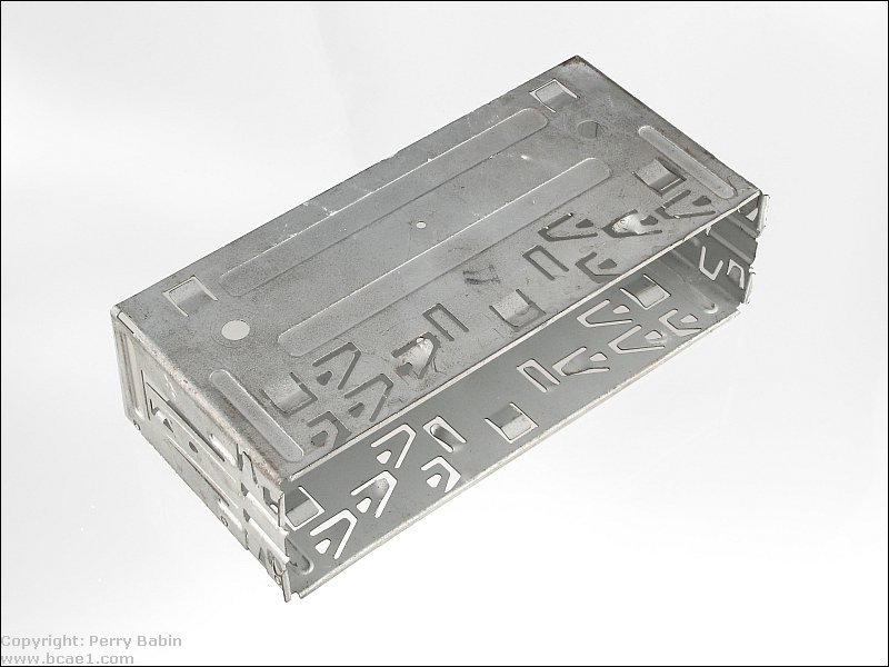
Securing the Head Unit:
There are several ways to mount aftermarket head units. The most universal way to mount a head unit is with the sleeve that's supplied with most head units. The sleeves have several (10-20) tabs that are bent behind the dash panel after the sleeve is inserted through the panel. Most sleeves are made for specific head units (or at least for specific lines of head units) and only fit those head units properly. When using this type of mounting, it's often necessary to use a backstrap for additional support at the rear of the head unit. When you use a backstrap, you'll need to screw it into the back of the head unit. Don't use a screw that's too long. You only need to engage 4-5 threads (at most). Long screws can damage the CD/DVD mechanism or circuit boards which could make the head unit unrepairable.
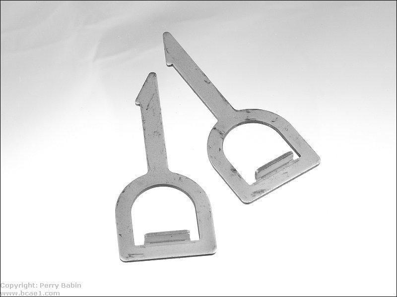
Most sleeves have locking tabs so that the head unit cannot be pulled out (or fall out) of the sleeve. To remove them, keys (supplied with the head unit) are required to unlock the head unit. One key is inserted on each side of the head unit (trim ring removed) and then pulled out. In some instances, after inserting the keys, the head unit has to be pulled out to free the keys.
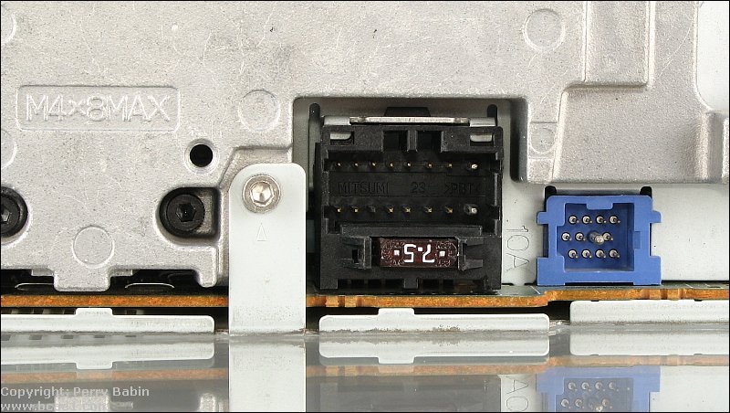
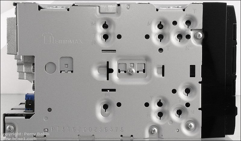
The best way is to mount a head unit is to use the ISO brackets that the original head unit used (or that can be purchased from one of the installation kit manufacturers like Metra). These will mount to the sides of the radio in holes that are laid out in the same pattern as those on the OEM head unit. When using these mounting holes, it's VERY important that you do NOT use screws longer than those that were used in the original head unit, those that were included with the aftermarket head unit or those supplied with the kit. Screws that are to long can easily be driven through a circuit board or into the CD/DVD mechanism which could make the head unit a paperweight (no warranty will cover this type of damage). On the side of the following head unit, you can see that the holes are marked (M, T, N). These markings indicate the OEM manufacturer (Mitsubishi, Toyota, Nissan) and the OEM bracket for your vehicle should align with the corresponding holes. When mounting this way, the head unit will almost certainly be positioned properly in the opening in the dash. The head unit's trim ring (bezel) should cover the gaps around the head unit.
Reset Button:
On most head units, there is a reset button. Sometimes, when power is interrupted to the head unit's 'constant' power wire (yellow on most head units), the microcontroller can get 'confused' and the head unit won't power up. If this happens, pushing the reset button can sometimes reset the processor and allow the head unit to function correctly. Bear in mind that this will wipe all memory from the head unit. You will lose all radio station presets, equalizer settings, crossover settings... so this shouldn't be done without troubleshooting a bit. Confirm that the head unit has both constant and switched voltage on the yellow and red wires. Also make sure that it has a good ground. The reset button is generally barely visible and is sometimes behind the flip-down face of the head unit. Some have no markings. All you will see is a small (1/16") button that's flush with the panel (or sometimes slightly recessed).
Another way to reset the head unit is to remove all power from it. This happens almost immediately for most head units but sometimes it takes a bit longer. Virtually no head unit will take more than a minute to be reset. It's important that you understand this will reset all settings because some people will start setting crossovers, equalizers, the clock... before they have the head unit completely installed. If they have to disconnect it from power (to route the wires the way they need to be), all settings will be lost.
----- Critically Important -----
Flash graphics viewing/use alternatives:
Flash support by most modern browsers has been dropped but that's not the end of the line for Flash.
There is no practical alternative to Flash for the interactive demos/applets/graphics on this site.. Especially when there are alternatives, some simple, some good, some...
Ruffle is chosen by most because they can't imagine using anything but their preferred browser. It works. It's OK but not great. The Flash graphics won't look as they're supposed to but it, generally, works.
The #1 preferred (by me) way to view the site and the Flash graphics is with the Chromium Portable browser and the installation of the older (no time-out) Flash Player files. This was incredibly simple when people knew computers but not today when people only know how to work with their phones.
The Flash Browser is a good option but it's so stripped down that it makes it somewhat difficult to use.
The Maxthon browsers are an option. The v4.95 is the easiest (install and use). V5.3.8 and 6.1.0 require (very) slightly more effort (very).
The Chromium and Maxthon browsers on the page above are 'portable' browsers. They are not installed into your system. They are simply made available for use on your computer. They can be carried around on a Flash drive and used on any computer.
This site was started for pages/information that didn't fit well on my other sites. It includes topics from backing up computer files to small engine repair to 3D graphics software to basic information on diabetes.
This site introduces you to macro photography. Macro photography is nothing more than the photography of small objects. It can take quite a while to understand the limitations associated with this type of photography. Without help, people will struggle to get good images. Understanding what's possible and what's not possible makes the task much easier. If you need to photograph relatively small objects (6" in height/width down to a few thousandths of an inch), this site will help.
If you're interested in air rifles, this site will introduce you to the types of rifles available and many of the things you'll need to know to shoot accurately. It also touches on field target competition. There are links to some of the better sites and forums as well as a collection of interactive demos.
This site helps anyone new to computers and anyone with a basic understanding of computers with a desire to learn more about the internal components of a computer. If you have a computer that you'd like to upgrade but don't know where to start, this is a good site for you.
This site is for those who want to begin racing karts but don't fully understand how the various parts work. It's mostly interactive demos that show how the various parts of the kart work.
Click HERE to visit a friend's new car audio tech site.


