Audio Systems:
This page will cover as many different system configurations as possible (until I get tired of drawing the diagrams).
Note:
The proper fusing for the amplifiers is NOT shown. Please read the fuses and amplifiers pages of this site for tips on proper amplifier installation. The head unit page will also give you some important information and may help you install your HU without murdering it. :-)
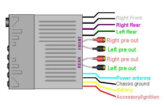
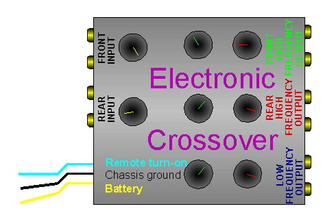
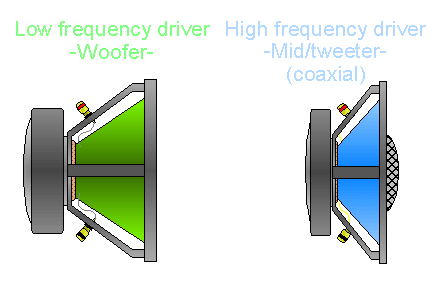
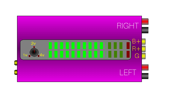
These first few diagrams will allow you to get a good clear look at all of the connections on the devices which will come later later on this page. These components will be much smaller in the later diagrams.
This is the head unit and all of its connections.
This is the electronic crossover.
These are the speakers.
This is the amplifier.
Basic System
Head Unit, 1 Amp and 4 Speakers
Head Unit, 1 Amp and 4 Speakers (all on amp)
Head Unit, 1 Amp and 4 Speakers (2 subs on amp)
Head Unit, 2 Amps and 4 Speakers (2 subs on one amp)
Head Unit, External Crossover, 2 Amps and 4 Speakers
Head Unit, External Crossover, 3 Amps and 4 Speakers
Start of 4 Channel Amplifier Section
Basics of 4 Channel Amplifier
Basic System with a 4 channel Amplifier
A 4 channel Amplifier system with 4 Channel Input
4 Channel amplifier with Bridged Rear Channels
4 Channel amplifier with Both Front and Rear Channels Bridged
4 Channel amp on front speakers, 2 channel amp on subs
OK, Now to systems.
The following is the most basic system. It involves a head unit (HU) and 2 pairs of speakers which are driven by the head unit's internal amplifier. You can see that the battery terminal of the HU is connected to a constant source of power (the battery) with an inline fuse. The accessory wire for the HU is connected to a power source which only has power when the ignition switch is in the 'on' or 'acc' positions. The battery and accessory connections will not be shown in the following diagrams but will be the same for all of the systems. The lines point to the speakers but the exact connection isn't shown. The colored speaker wires from the HU are going to be connected to the positive speaker terminal of the speaker. The black or darker speaker wire will be connected to the negative speaker terminal. Of course, this is just a generic type of diagram and you should consult the wiring diagram which was supplied with the HU.

Using the HU's internal amplifier and an external amplifier:
In this diagram, you see that the front speakers are being driven from the HU's internal amplifier and a pair of rear speakers are being powered by an external amplifier. This type of system has very little chance of sounding good. If the amplifier is being used because more volume is desired and the front and rear speakers are roughly equivalent in efficiency then the front speaker's amplifier will probably be driven into clipping well before the external amplifier reaches clipping. If the HU's fader is turned toward the rear (amplified) speakers, you may get better sound quality (or at least less clipping from the internal amplifier) but the image will be from the rear of the vehicle which is generally undesirable. Many people run tweeters from the internal amplifier but this also generally leads to less than optimum sound quality. Not because the internal amplifier is of poor quality but because it will be driven into clipping if the output of the tweeters is to keep up with the speakers which are driven by the external amplifier.
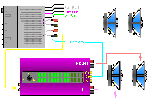
Since most amplifier are capable of driving 2 pairs of speakers, I would strongly recommend driving all of the speakers from the external amplifier. (like this)
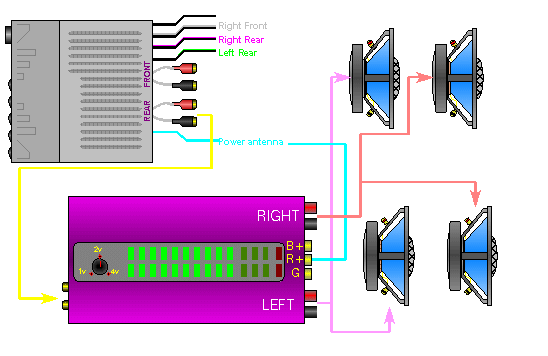
This system has a better chance of sounding good than the system which had the amplifier driving the rear full range speakers. If the amplifier has a built in crossover, you'd set the crossover for low pass and probably to about 90 or 100 hertz (if there's a choice). You still won't be able to get very high SPL before the HU's internal is driven into clipping but if you only need to pick up the bottom octave or so of the audio spectrum, this may do a good job.
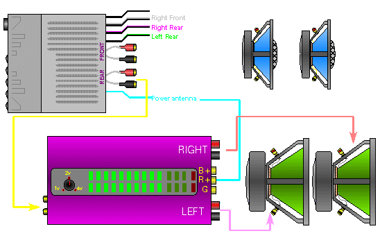
Note: The remote/power antenna wire won't be shown on the following diagrams but you obviously have to connect it in a real installation.
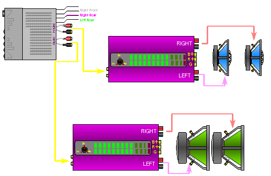
This diagram shows how you'd connect 2 amplifiers if the amplifiers had internal crossovers. You would set the crossover on the top amplifier to high pass and the crossover on the bottom amplifier to low pass. You could adjust the levels of each amplifier by using the HU's fader control or with the gain controls on the individual amplifiers.
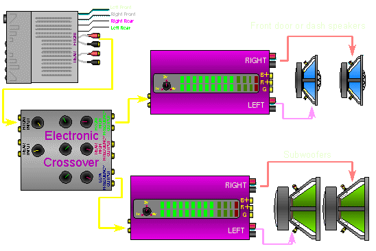
In this diagram, we are using an external crossover. To control the levels between the front/high frequency speakers and the subwoofers so that the system sounds 'balanced' (not too much or too little of either), you could adjust the levels on the crossover or use the gains on the amplifiers. It's generally, but not always, easier to use the crossover's level controls. In this configuration, since we are using a single set of RCA cables, you'd have no control over the levels of each amplifier from the head unit. Some crossovers have a third input which would allow you to connect the other set of RCA outputs (from the head unit) to the crossover (into a subwoofer input jack). This would allow you use the fader to adjust the levels between amplifiers.
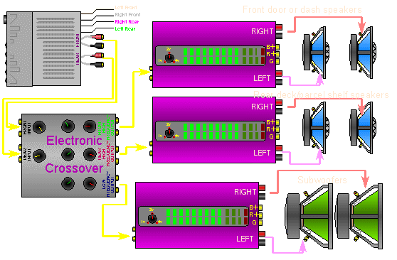
In this diagram we see that we have a seperate amplifier for the front, rear and low frequency speakers. We are using both sets of RCA outputs from the HU. The RCA patch cables go to the front and rear inputs of the crossover. The front outputs of the crossover go to the amplifier which drives the front speakers. The rear outputs go to the amplifier which drives the speakers in the rear deck. The crossover's subwoofer output goes to the subwoofer amplifier. On most crossovers, the fader will still operate through the crossover which would allow you to balance the levels of the front and rear speakers from the head unit. Many crossovers mix the low frequencies of the front and rear input signals and send both of them into the subwoofer section of the crossover. This makes sure that you have low frequency output no matter what the fader position.
You May Be Interested in My Other Sites
-
This site was started for pages/information that didn't fit well on my other sites. It includes topics from backing up computer files to small engine repair to 3D graphics software to basic information on diabetes.
-
This site introduces you to macro photography. Macro photography is nothing more than the photography of small objects. It can take quite a while to understand the limitations associated with this type of photography. Without help, people will struggle to get good images. Understanding what's possible and what's not possible makes the task much easier. If you need to photograph relatively small objects (6" in height/width down to a few thousandths of an inch), this site will help.
-
If you're interested in air rifles, this site will introduce you to the types of rifles available and many of the things you'll need to know to shoot accurately. It also touches on field target competition. There are links to some of the better sites and forums as well as a collection of interactive demos.
-
This site helps anyone new to computers and anyone with a basic understanding of computers with a desire to learn more about the internal components of a computer. If you have a computer that you'd like to upgrade but don't know where to start, this is a good site for you.
-
This site is for those who want to begin racing karts but don't fully understand how the various parts work. It's mostly interactive demos that show how the various parts of the kart work.
Multi-Channel Amplifiers
Multi-channel amplifiers are essentially the same as a stereo amplifier except for the fact that they have more than 2 channels. Now this may seem fairly obvious to some people but you must remember that this site is designed for people who are new to car audio. This section will (hopefully) clear up any misconceptions or confusion about multi-channel amplifiers in general.
Generic 4 channel amplifier:
Basics:
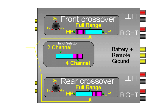
- As you can see on the 4 channel amplifier below, there are 4 input jacks and 4 sets (+&- terminals) of corresponding speaker output terminals.
- There is also an input selector which allows you to use only 2 inputs to drive all 4 channels without having to use all 4 input jacks. When the switch is in the 2 channel input position, only 2 inputs (1 right and 1 left) are required to drive all of the channels. When the switch is in the 4 channel position, all 4 channels have to be driven seperately and are independent of each other.
- You can also see that there are 2 crossover selector switches. They allow either pair of channels (front or rear) to play either a full range signal (which will pass the entire input signal to the amplifier section), a high pass signal (blocks out the low frequencies) or a low pass signal which blocks out the high frequencies but allows the bass to play through. Now these are the simplest of built in crossovers. They don't allow you to select the crossover point or slope. Some amplifiers allow you full adjustment of all parameters but for this example, I chose to only show this type (read: I was too lazy to draw anything fancier). On this amplifier, the front 2 channels are set to high pass. The rear channels are set to low pass and the input selector switch is set to 4 channel which means that all 4 channels will have to be driven individually (all 4 input jacks will have to be used).
Basic System:
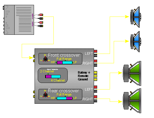
In this diagram, you can see that one set of pre out jacks from the head unit are connected to the front inputs of the amplifier. To allow all 4 channels to be driven, the input selector is set to 2 channel. The front channel crossover is set to high pass. The front channels are used to drive a pair of coaxials. The rear channel crossover is set to low pass and the rear channels are being used to drive a pair of subs. In this type of system, the relative output levels would have to be set with the gain controls on the amplifier.
4 Channel Input:
In this diagram, all 4 input channels of the amplifier are being driven independently. The input selector is set to 4 channel. Everything else is the same as the previous diagram. This setup would be a little better than the previous diagram because you could adjust the relative levels of the coaxial speakers and the subs through the use of the fader control on the head unit.

Bridged Rear Channels:
This diagram shows the rear channels bridged. When bridging an amplifier, you must make sure that the total impedance of the speakers is not too LOW for the amplifier that you're using. If you're confused about the impedance of multiple speaker loads, try reading either this link or this link.
Both Front and Rear Channels Bridged:
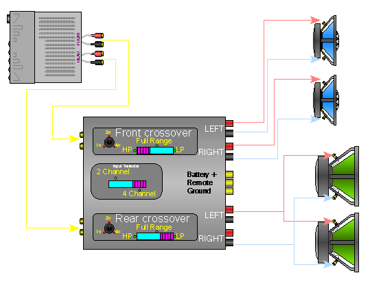
This diagram shows how you might use the amplifier with both the front and rear channels bridged. You can see that the rear preamp output channels of the head unit are connected to the 4 channel amplifier AND the input selector is set to 2 channel AND BOTH crossovers are set to low pass. The front pre outs of the head unit are connected to separate amplifier which is being used to drive the front/high frequency speakers. The relative output levels of the high and low frequency speakers would again be adjustable through the fader control of the head unit.
4 Channel amp on front speakers 2 channel amp on subs:
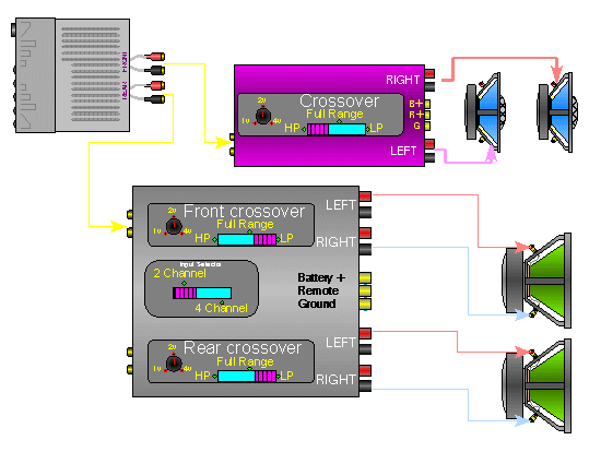
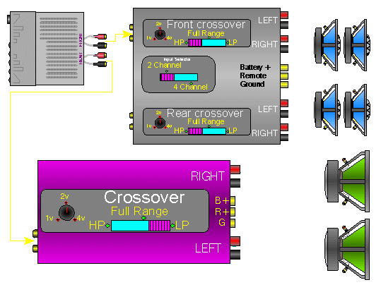
This diagram shows how you could use the 4 channel amplifier on the high frequency speakers and a second amplifier on the subs. Note the crossover settings on each of the amplifiers.
|


