
|
| Email Home Page |
|
|
|
|
| Email Home Page |
|
|
|
----- Critically Important -----
Adobe has deemed that the Flash content on web pages is too risky to be used by the general internet user. For virtually all modern browsers, support for Flash was eliminated on 1-1-2021. This means that those browsers will not display any of the interactive Flash demos/calculators/graphics on this (or any other) site.
The simplest (not the best) fix, for now, is to download the Ruffle extension for your browser. It will render the Flash files where they were previously blocked. In some browsers, you will have to click on the big 'play' button to make the Flash applets/graphics visible. An alternative to Ruffle for viewing Flash content is to use an alternative browser like the older, portable version of Chrome (chromium), an older version of Safari for Windows or one of several other browsers. More information on Flash capable browsers can be found HERE. It's not quite as simple as Ruffle but anyone even moderately familiar with the Windows Control Panel and installation of software can use Flash as it was intended.
Click HERE to open this graphic in a new tab. Right-click to zoom. Left-click to drag.
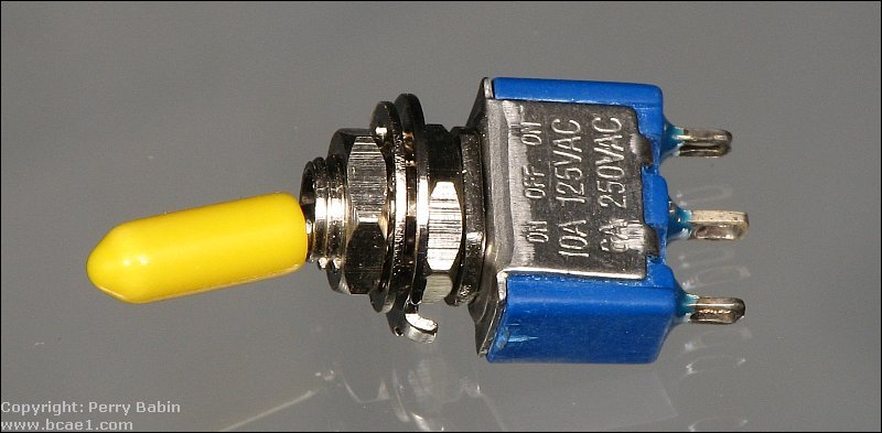
This is an example of a single pole double throw toggle switch. You can see that the basic specifications are stamped into the body of the switch. This small switch has an exceptional current capacity. Generally, switches this size are rated for no more than 3 amps.
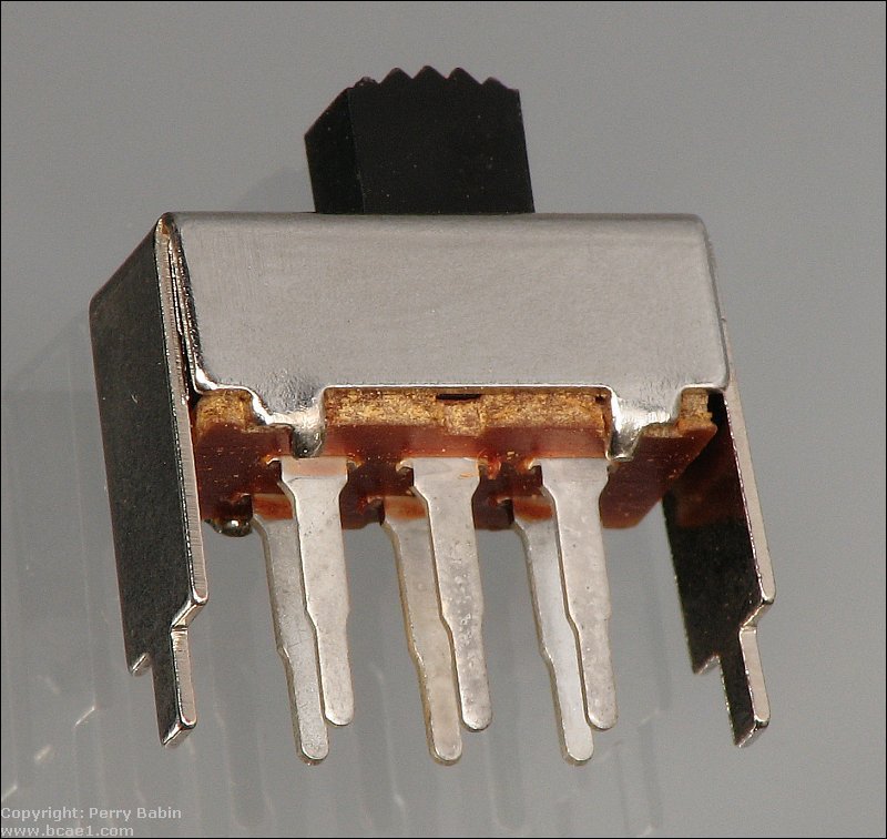
 The switch below is a double pole double throw (DPDT) slider switch. This switch has 2 independent circuits. The sliding contact connects 2 of the 3 terminals for each half of the switch. The position of the slider determines which 2 terminals are connected.
Click HERE to open this graphic in a new tab. Right-click to zoom. Left-click to drag.
This is a switch like the one in the previous image. This one has solder tabs on the body of the switch that allow it to be soldered into the board.
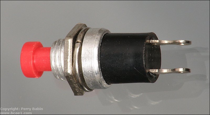
This diagram is a cut away view of a normally open pushbutton switch.
Click HERE to open this graphic in a new tab. Right-click to zoom. Left-click to drag.
The real thing.
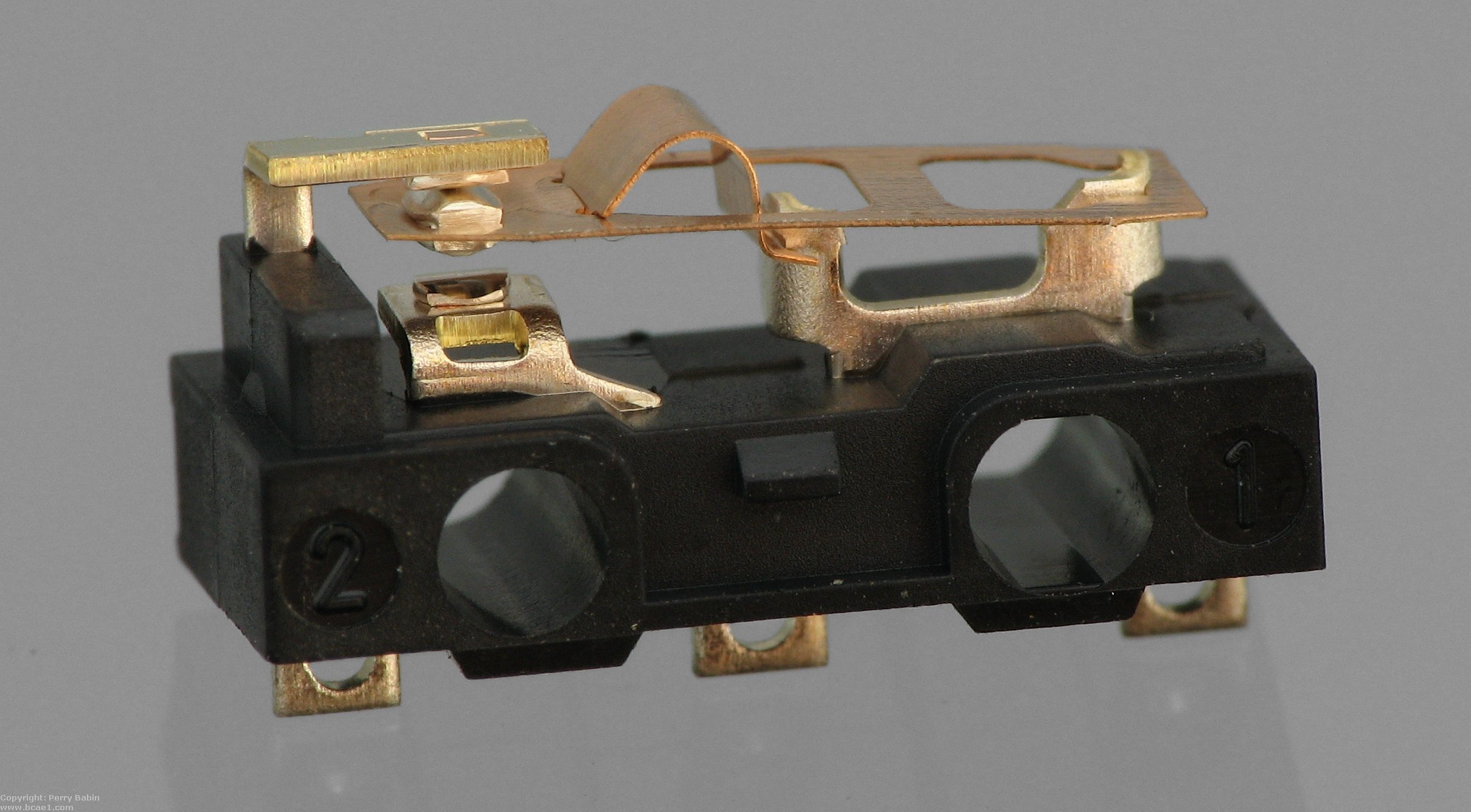
 The following switch has a lever actuator. These are used in many applications. Some have been used in the mice used with computers (without the lever). Some are used as limit switched. The ones used as limit switches often have very long, flexible levers (sometimes in the form of a stiff wire) so that the switch isn't damaged if the mechanism goes a bit beyond the desired limit.
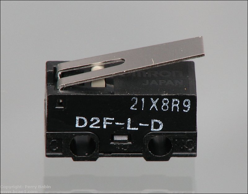 This is the snap-action mechanism that ensures that there is sufficient pressure between the contacts. It's a variation on the mechanism used in standard toggle switches. This photo is taken from the opposite side of the switch compared to the photo above. Click on the image to open a larger version in a new window. Click the photo in the new window to show it full size (works in most browsers). For scale, this switch is 1/2" long.
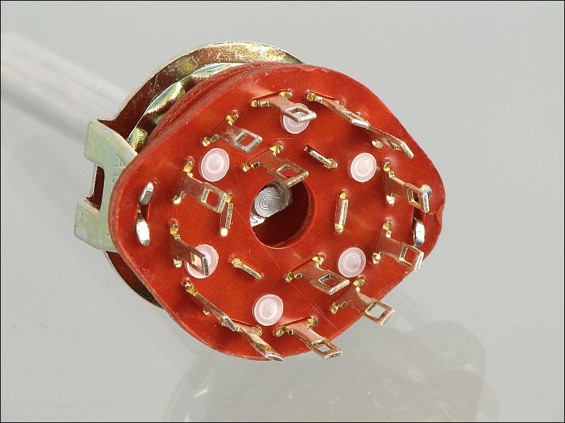
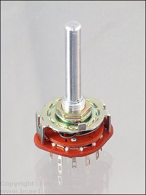
The bottom of the switch has two rings of terminals. Here, the inner ring has only 2 terminals because it's a two pole switch. The outer ring has 12 terminals (two sets of terminals, each with 6 contacts for the 6 positions).
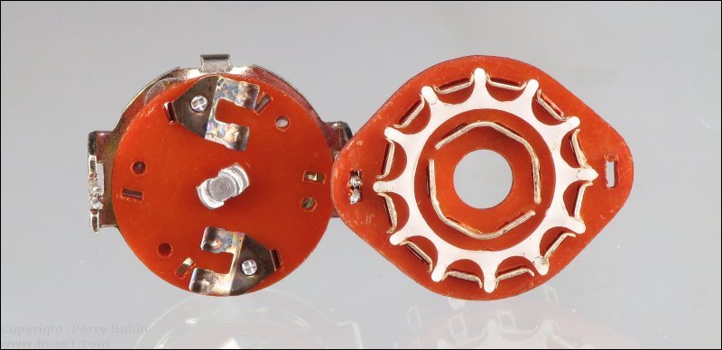
 This switch has two movable contacts or 'wipers' that slide along on stationary contacts. There is one pair of wipers for each set of contacts. The stationary contacts are connected to the terminals on the back of the switch. The stationary contacts for the center ring of terminals is a long contact that, for this switch, spans nearly 180�. For the outer ring of terminals, you can see that there are multiple short contacts. For each switch position, for each independent circuit, one outer terminal is connected to the terminal on the inner ring on the back of the switch. If you look at the image below, you can see everything described above. Click HERE to open a larger version of this image.
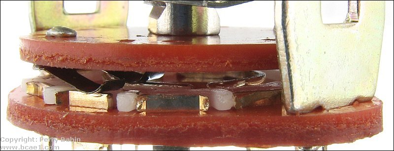 In the image above and in the image below, you can see that there is a white plastic component between the contacts. This is an insulator. Some rotary switches are make-before-break and others are break-before-make. This is a break-before-make. Without the insulator, the outer part of the wiper would drop down in the gap and short the adjacent terminals as the switch's position was changed. This would be very bad if the switch was a selector that was used to select different power supply voltages (all produced by independent power supplies). In some instances, however, you don't want to lose complete contact with the outer terminals. One example is when you have a large switch (battery isolator, for example) and the switch is switching from one battery to another. Completely losing power to the engine/alternator between positions could cause problems with the computer or engine. Battery isolators are commonly used in boats.
The demo below shows a system with multiple ways to control the amplifiers and fan. The top amplifier is controlled solely by the head unit's status (on or off). The head unit's remote output controls the relay. The relay's output terminal (terminal 30 in this case) is connected to the top amplifier's remote input. When the head unit is turned on, the relay is energized and power is sent to the top amp's remote turn-on terminal. When the relay is energized, power is also sent to both of the toggle switches. If the toggle switch is in one position, the amp or fan will be off. If the switch is in the opposite position, the amp or fan will turn on/run. When the head unit is switched off, the relay is switched off and everything goes off. To toggle the switch position, click on either side of the handle.
Click HERE to open this graphic in a new tab. Right-click to zoom. Left-click to drag.
At this point, assuming that you've done as suggested and read through the directory in order from top to bottom, you know that the wire from the battery MUST be fused with a properly rated fuse (depends on the wire size) and that the fuse must be within 18" of the battery. For 14g use a 15 amp fuse. For 12g wire, use a 20 amp fuse. The individual fuses for each circuit should be the minimum size possible. If the neon (or any other accessory) pulls 2 amps of current, use a 3 amp fuse. If it pulls 3-4 amps, use a 5 amp fuse. There is no advantage of using a fuse that's significantly larger than necessary. In the diagram, all of the fuses are the same but you would use fuses that are appropriate for the wire leading from the output terminal to the device being powered. The Fuse and Wire pages have more information if you don't fully understand the consequences of using the wrong fuse.
Click HERE to open this graphic in a new tab. Right-click to zoom. Left-click to drag.
When buying a lighted rocker switch, there are a few things you should know. There are lighted rocker switches for 12v and 24v DC as well as lighted rocker switches that are designed to be used with household mains voltage. Lighted switches have to be selected for the type of electrical system you have for them to work properly. While the contacts may be able to work with both AC and DC voltages, the lights inside the switches won't. If you use a lighted switch that's intended for low voltage DC on a 120/240v mains circuit, the light will be instantly burned out and there could be a risk of an electrical fire. The light in an AC switch won't be damaged if used in a DC circuit but it won't light. You should also know that there are some illuminated rocker switches that use LEDs instead of incandescent lamps. For those switches, there may not be as much flexibility in the various wiring configurations because the LEDs are polarity sensitive. In the following demo, you can open and close the switch. For the normal connection, the internal lamp (could be an LED) lights only when the external lamp is powered (when the switch is closed). For the alternate connection, the internal lamp is always powered. The external lamp is lit when the rocker switch is in the closed position.
Click HERE to open this graphic in a new tab. Right-click to zoom. Left-click to drag.
In the switch above, you can see that there is a dark component in place of one of the contacts. In this particular switch, it's simply an insulator (again, this is not a depiction of a real switch, just a close approximation). Switches will have various ways of breaking contact to the ground terminal. This 'dummy' contact was the simplest for the demo.
Note: The following switch (CW part #: GRB292A301BBAG1) is a bit different from most lighted rocker switches. This one has two LEDs (one amber and one green). The amber LED is independent of the switching mechanism. The green LED can be wired like the light in the Flash demo above (LED always on or only on when the switch contacts are closed). Since there is a second LED, there is no reason to wire it to be on constantly. The amber LED could be wired to the illumination circuit of the vehicle so that the switch would be visible at night even when the switch contacts were open. This switch was purchased from Digi-Key. The D-K part number is CW141. This switch is marked as being a 14v switch. Lighted rocker switches marked as 12 or 14v switches will work in vehicles (cars, trucks, boats...) with 12v charging systems.
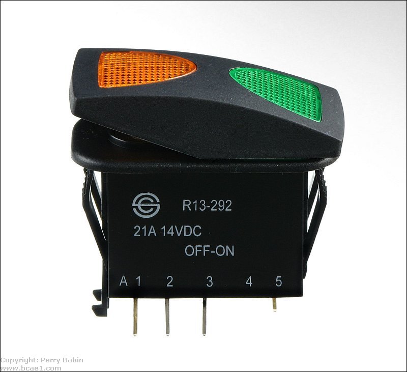
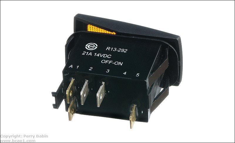 The circuit below is from the switch above. As you can see, the bottom two terminals are connected to ground. They must be connected to ground instead of the positive voltage because LEDs are polarity sensitive and won't light up when connected backwards. THIS is the datasheet for this switch. If you look closely at their diagram, the LEDs are backwards. This is one more thing that can make wiring a lighted rocker switch confusing. Fortunately, the positive/negative markings are correct.
Click HERE to open this graphic in a new tab. Right-click to zoom. Left-click to drag.
|
|
You should remember: 1.A switch is an electromechanical device used to make or break an electrical connection. |

|

|
|

|
 A switch is an electromechanical device that's used to open or close an electrical circuit. They are available in a number of configurations. For now, we will only discuss a simple single pole double throw switch (SPDT). The number of 'poles' indicates how many completely independent circuits are controlled by the switch. The number of 'throws' indicates the number of positions that will result in an electrical connection. The diagram below shows some of the internal components of a SPDT toggle switch. This is not the internal structure of any real switch, but it's a close approximation of the way many of the toggle switches function. Many single pole double throw toggle switches have only two positions. Both result in a circuit being completed inside the switch. This switch has a third position that allows you to have no electrical connection between any of the terminals. In the 'off' position, the movable internal contacts are not connected to either of the outer (left/right) contacts. Clicking on the buttons will change the position of the switch to allow you to see how the internal components work. When you click the left button, current can flow between terminals B and C. When you click the right button, current can flow between terminals A and B.
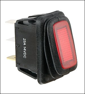
 The lighted switches in the previous diagrams were SPST models. I recently bought some lighted switches (example to the right) that could not be wired as shown in the 'alternate connection' above. The switch was a modified SPDT but was marked as a simple on/off switch (SPST). This means that the power source would be connected to ground if connected as in the 'alternate connection'. If you're unsure about your switch, you can check it with an ohm meter. If you find that the resistance between the center terminal and the ground terminal is near zero ohms in either switch position, the switch is a SPDT and can be wired only one way (light on only when load is connected to power).