|
Building a Basic Computer - Part 2
|
This page is being updated. THIS is a link to the old Building a Basic Computer - Part 2 page.
|
If you're interested in seeing it, THIS is the owner's manual for the motherboard used here.
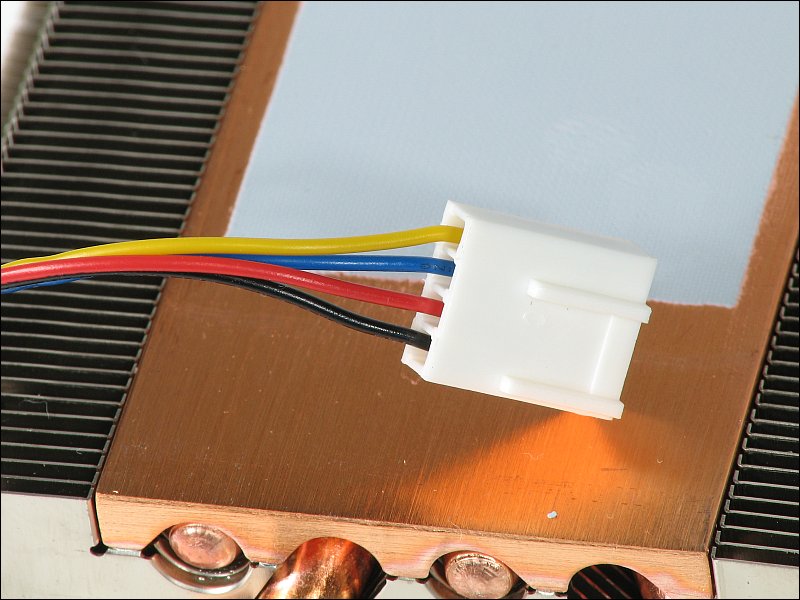
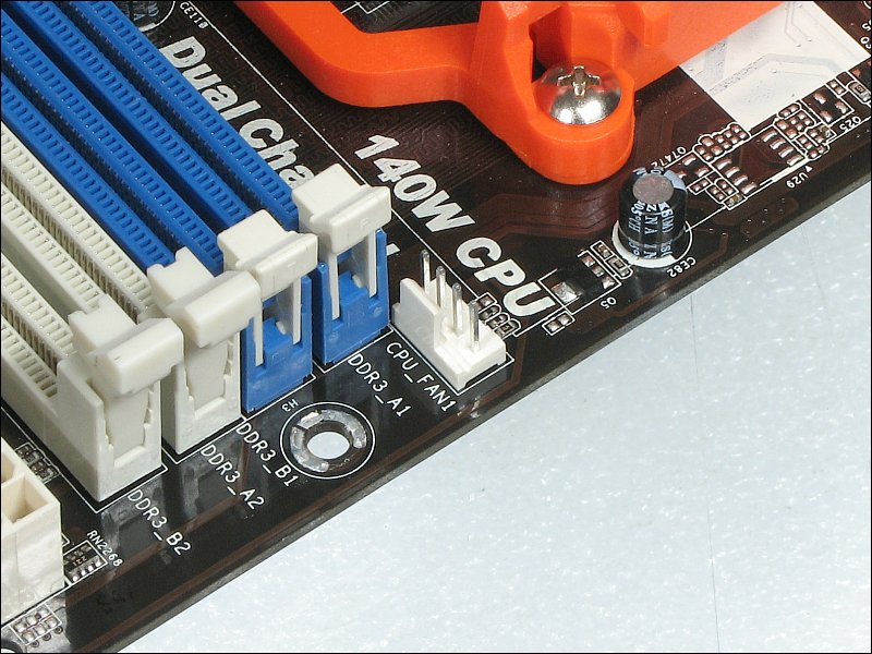
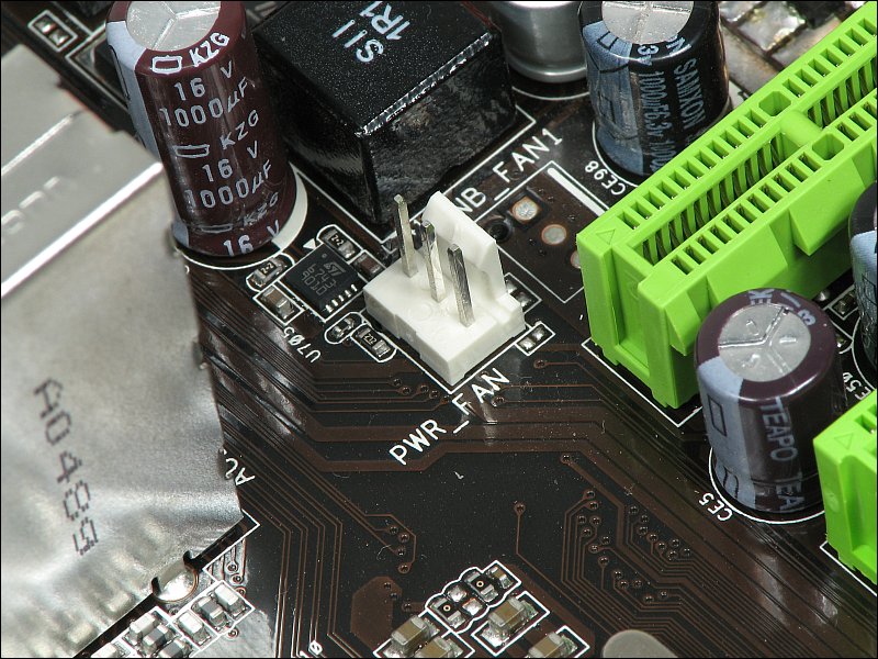
On the previous page we mounted the heatsink on the CPU. For most CPU/heatsink combinations, the heatsink alone will not keep the CPU cool. Most have fans which must be connected to a power source. Below, you can see the connector for the fan on this computer. For the computer's power supply, the yellow wire is the +12v wire and the red wire is the +5v wire. This is true for any AT or ATX computer power supply. For fans, the wire colors are different. The red wire is the 12v wire and the black wire is ground. This is likely due to the fact that DC power generally uses red for the positive supply and fans were in use long before computers came to be. For 3-wire fans, there is an additional wire. That's the tach wire. Here, it's a blue wire (this is an AMD fan). On some aftermarket fans, the tach wire will be a different color. No matter the color, you know that the wire in position 3 is the tach wire. Looking at the plug, you can see that the lock is centered on those three wires. This allows it to be compatible with the standard 3 pin fan header. Below, the fourth wire is the PWM wire. Many motherboards have both 3 and 4 pin fan headers. If you have a 4-wire fan and an available 4-pin CPU fan header, use it. If your motherboard has only a 3-pin header, you can use it with the 4-wire fan but there won't be any PWM fan control. In the second image, you can see the header for the CPU fan.
More on PWM fan control: To understand PWM at the simplest level, imagine having a fan with it's black wire connected directly to the ground terminal of the power source and the red wire through a pushbutton switch to the positive terminal of the power source. The power source could be a battery, a computer power supply or anything else that could supply the fan's rated operating voltage. When you push the switch, the fan turns and if you hold it long enough, the fan will reach full speed. If you push it once for a short period (releasing it well before the fan reaches full speed) the fan will increase in speed while the button is held down and slow down when released. If you held the button down for 1 second then released it for one second and repeated it, the fan would reach some given speed and continue to run at that speed. If you used one second as the 'cycle' for each switching action, and you held it down for ½ second and it was released for the other ½ second, the fan would spin at half speed (approximately). This would be a 50% duty cycle (50% of the time, the power was applied/connected to the fan). The 'duty cycle' is the percentage of time that the voltage is applied. If it's applied 50% of the time, it's a 50% duty cycle. If it's applied 20% of the time, it a 20% duty cycle. If you held it down for ¾ of a second, the duty cycle would be 75% and the fan would spin faster yet. At 100% duty cycle, the voltage is constantly applied and the fan spins runs at full speed. When the motherboard senses that the temperature (for the CPU, in this example) is too high and the fan needs to run faster, it increases the duty cycle (on PWM fan controllers). One of the greatest advantages here is the fact that the fan can be controlled by a 'signal'. That's different than the older way of controlling a fan where the voltage was regulated and the fan's voltage regulator had to supply all current to the fan. Here, 1 second cycle times were used for simplicity. For the PWM dive circuit, one cycle is 1/25,000 of a second (if the drive frequency is 25,000Hz).
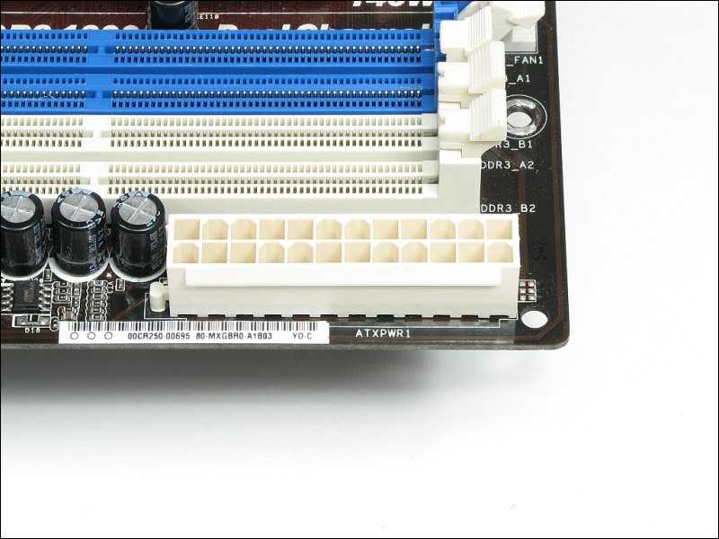
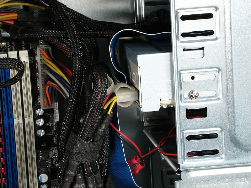
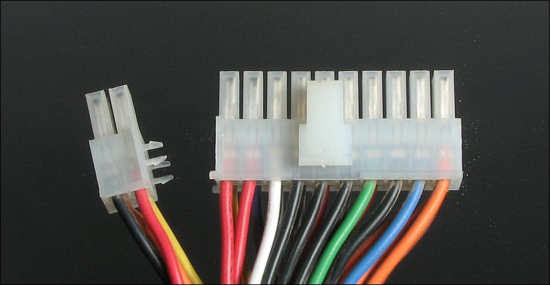
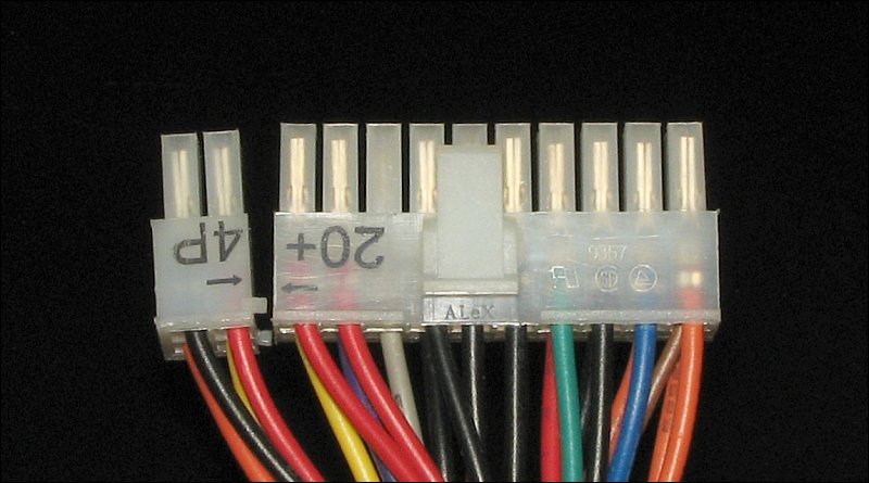
You will have to make at least one power connection from the power supply to the motherboard. Virtually all modern computer motherboards have 24 pin power connectors. The exceptions would be special form factor boards like the ITX boards (tiny motherboards, no expansion slots, low power processors...). To accommodate motherboards that don't have 24 pin connectors, most power supplies have 20+4 pin connectors. The 20 pin part of the connector has a standard lock on it so that it can't pull out of the motherboard. The 4 pin connector often latches onto the 20 pin connector to prevent it from pulling out of the motherboard. THIS one locks into the 20-pin part of the plug. THIS one has tabs that prevent it from pulling out. The 4-pin part is plugged in first then the 20-pin part is plugged in. When plugging it in, support the board from the back. These can be difficult to get locked in and may take a bit of force (more than the board should bear without support).
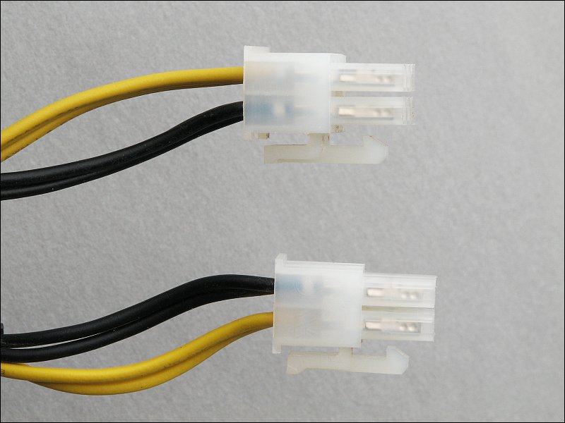
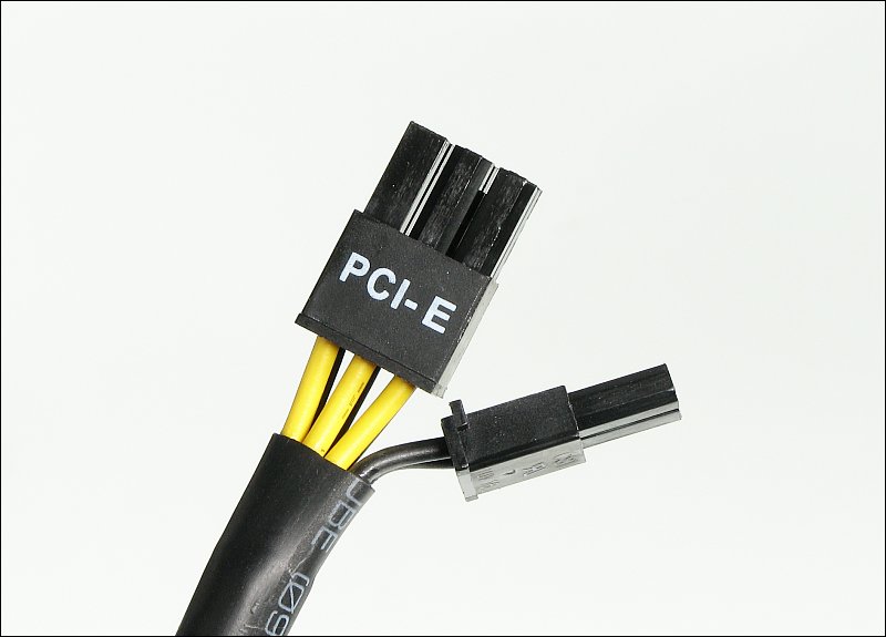
 There is another power plug on all but the simplest of motherboards. It feeds 12v to the switching regulator that produces the supply voltage for the CPU. With the 20/24 pin power plug, there's really nothing that you can get wrong. With this one, you can get things very wrong. The plug below is made to take one or two 4 pin plugs (one is generally enough but use two if your motherboard has two) or one 8 pin plug. Any of those configurations is OK. The problem is the PCI-E connector. It's a 6 pin plug and WILL fit this socket. The polarity is reversed on the PCI-E plug, compared to the ATX/EPS power plug. If you plug the 6 pin PCI-E plug into this socket, it's likely to immediately destroy the motherboard when the motherboard is switched on.
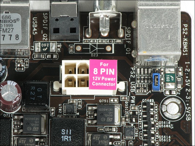 If you're not a geek, you'll likely want to skip this paragraph. I was curious about the fuses marked P 160 and P 260 in the photo above. They are resettable Polyfuses that protect the motherboard from damage if a defective or incorrect device is plugged into the various ports. The one marked P 160 is likely for the PS/2 ports. The marking of 160 means that it can hold 1.6 amps of continuous current. The following are the two plugs that can be plugged into that socket. The top is the PCI-E. The bottom is the 4 pin power plug that's supposed to go into the socket above. As you can see, looking at the clip as the reference, the plugs have reversed connections for the yellow and black wires. Most PCI-E plugs are marked but these have no markings. There are also 8 pin power plugs (one PCI-E and one for the CPU power supply). I don't know if those can be plugged in the wrong socket so I'll have to simply say be careful if you have unmarked 8 pin connectors. The 4 and 8 pin plugs for the motherboard will be marked EATX or EPS. Plugs marked PCI-E are for high-end graphics cards. If you have a 6-pin connector and it's bound (very close to the plug) to a 2-pin connector, it's a PCI-E plug.
 Although I've only seen it once, you may see it on other boards. To supply power to graphics cards that draw significant current but don't have PCI-E connectors on-board, there is a 4-pin molex connector on the motherboard near the PCI-E slots. You plug a standard 4-pin molex into that socket.
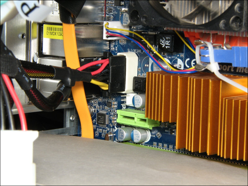
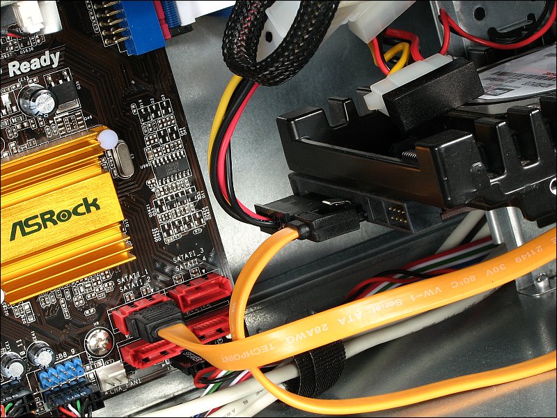
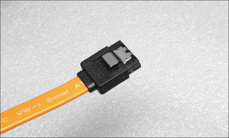
Most new computers will use SATA connections for the various drives in the computer. This includes the hard drives and optical (CD/DVD) drives. Below, the four red connectors are SATA II connectors (rated for 3GB/second data transfer. Newer/higher performance motherboards have SATA III instead of SATA II. The SATA III are faster and often require cables rated for SATA III. If you have to buy cables for SATA drives, you should buy cables with locking clips on the end connectors. SATA cables without the locks often pull out easily. Just remember that the connectors have latches on them when you have to unplug one. They can break the header on the motherboard is you pull without releasing the clip.
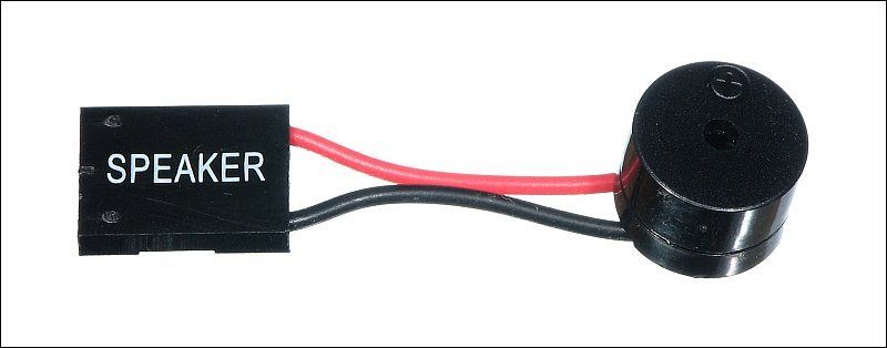
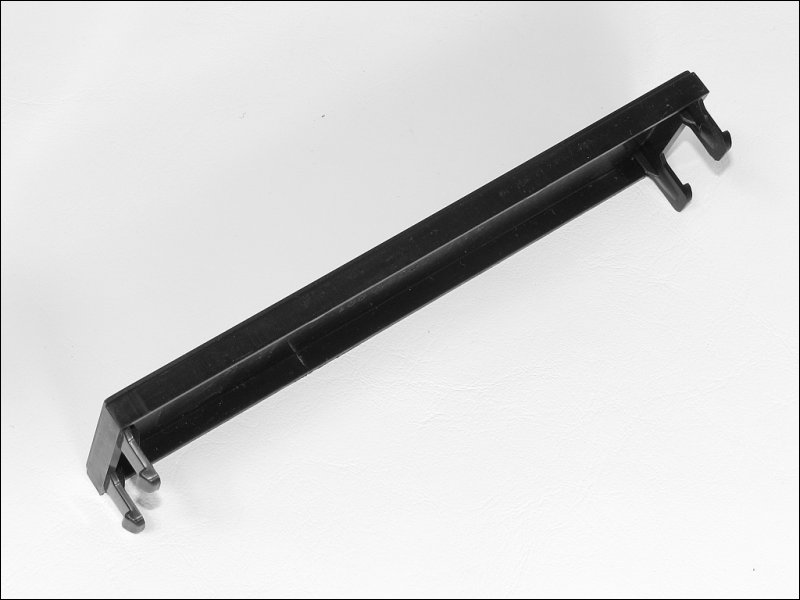
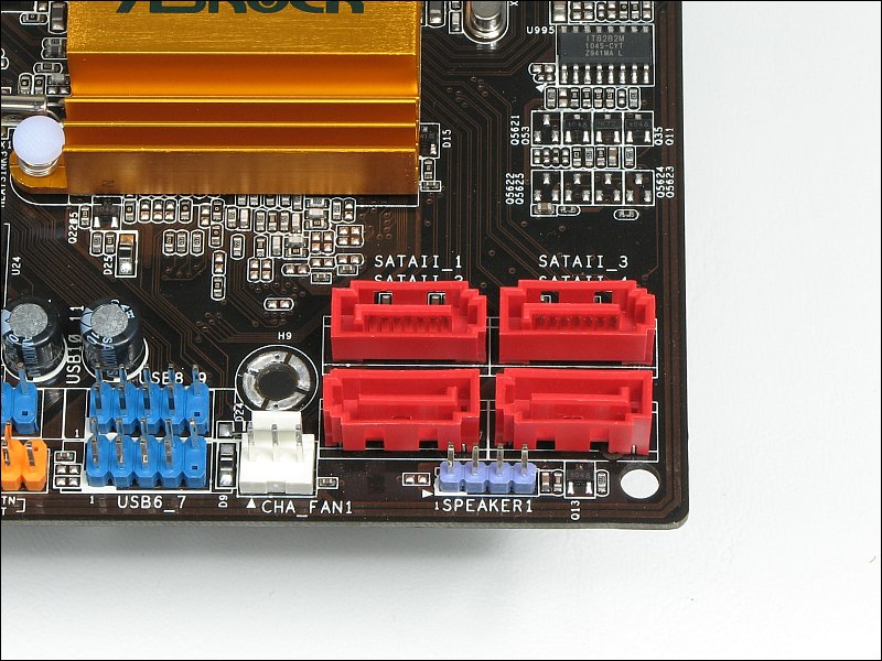 While we're here... Above, you can see the speaker header. The connector has 4 pins but only 2 are used. Many of the new cases have no normal speaker. Instead, they supply a device like the one below. It's really not a speaker but it can produce a beep to let you know that the computer has 'post'ed (passed the Power On Self Test). If the motherboard has a different type of connector (one with 2 individual, single-contact connectors), you will use the outer two pins of the header. When connecting this type of speaker, the red lead goes to pin 1. This may not seem like an important part of the computer but it is very important when you're powering the system up for the first time. If there are any problems, the system will produce a series of beeps as a code to tell you what the problem is. The most common fault is a problem with the memory but there are others and the speaker will allow you to determine what they are.
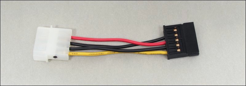
 Most new power supplies have enough SATA power connectors but that's not always the case (especially if you're upgrading an old computer). If you don't have enough SATA power connectors, you can use a 4-pin molex to SATA adapter cable. I personally prefer using the adapters because they're less stiff than the wiring for most SATA power connectors. This means that there is less stress on the (seemingly) fragile drive connectors.
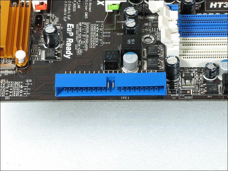
 If you have older hard drives or optical drives that have an IDE interface (blue connector below), you will have to use an IDE cable. If you haven't done so already, read the Storage Devices page. It has additional information on IDE cables that may be helpful. It has notes on the different types of cables and jumper settings.
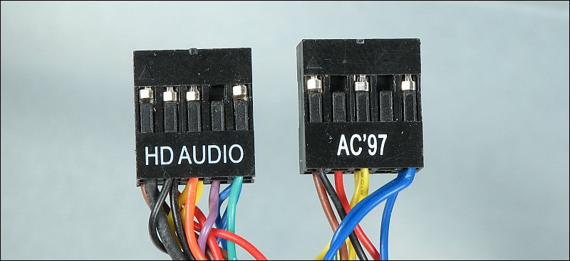
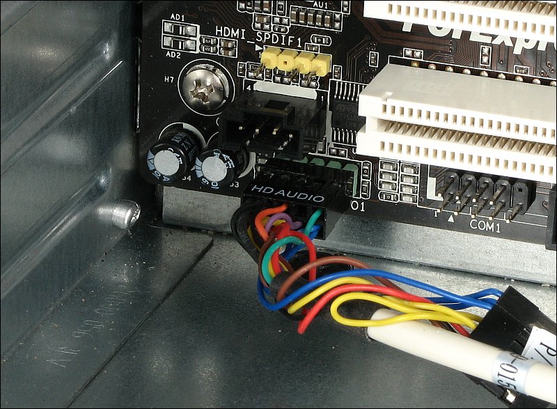
There are two types of front panel audio connectors. The older ones are marked AC97. The newer ones are marked HD Audio. The main difference in the two is that computers that have HD audio capability and use the plug have more options at the front panel. For AC97 audio, there is one mic jack and one headphone/audio jack. For HD audio, the mic jack can be used as a second headphone/audio jack. Also, when the motherboard senses that something has been plugged into the front panel jacks, it will switch the audio off for the rear audio output.
 Below is the audio connector on the motherboard. Notice that there is a missing pin. That's to prevent you from plugging in the wrong plug (USB, etc...) or plugging in the audio plug backwards.
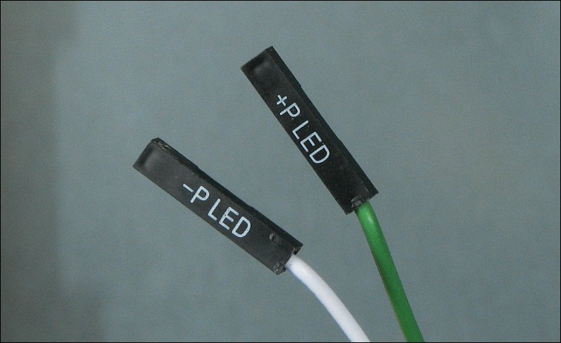
This next image shows the header (orange) for the front panel switches and LEDs. The connections for the switches can go either way (no polarity) but the LED connections must be correct for the LEDs to light up. On this board (and every other board, as far as I can remember), the positive terminal on the header is always on the end of the header with the pin designated as pin 1. Various cases will have different color schemes for the wiring. The most common color scheme has a colored wire (blue, orange, red...) and a white or black for each pair (one pair for each LED and one pair for each switch). The colored wires are the positive and the colors that are common to every pair (black or white) is the negative. For cases that use only black and gray wire colors, the black is the negative and the gray is the positive.
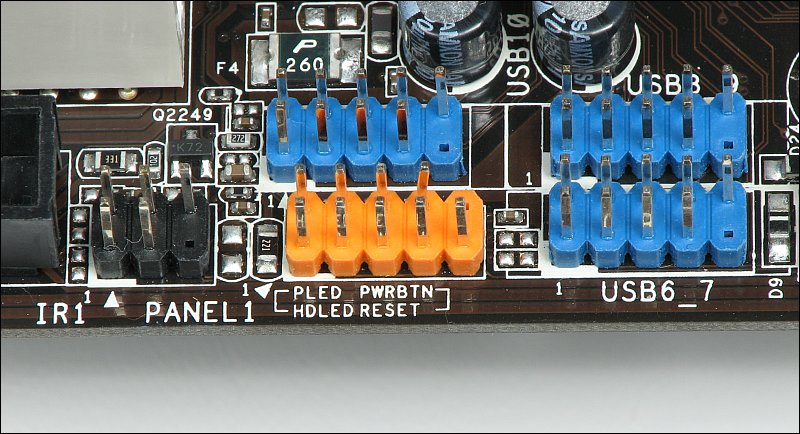 Some of the power LED connectors have individual plugs because some boards have a space between the positive and the negative header pins.
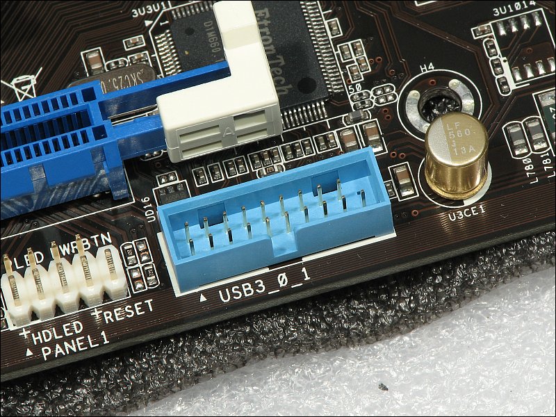
 Above, the blue headers are for the front panel USB 2.0 ports (different than the USB 3.0 ports). Again, these are keyed so that you can't install them the wrong way. Below, the header and plug are shown for the USB 3.0 front panel connectors. Since this is fairly new, not all cases have USB 3.0 ports. You can buy an add-on panel that has USB 3.0 ports but many times they plug into the back of the computer (you have to run them through an expansion slot outside of the case). This was included with mother board (different computer and motherboard -- Asrock 990FX).

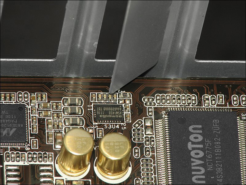
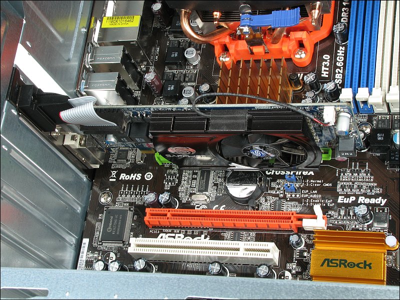
The expansion slots allow you to add functionality to the motherboard. In most cases, sound cards and video graphics cards are installed. It's also possible to install cards that can be used for setting up RAID arrays, improving the speed of your ethernet connection and/or adding eSATA ports to a computer that doesn't have them. These are just a few of the options. Here, you'll see the installation of a video graphics card. Before installing the various cards (video, sound, etc...) in the expansion slots, you'll have to remove the covers for each slot in the case. It's important that you don't damage the motherboard. Many times, there are very tiny components near the covers and when you're twisting the covers to break them free, it's possible to damage the components. This would require that you return the motherboard for a replacement (which may not be covered under warranty because it's not a manufacturing defect). The following shows how close the piece of sheetmetal was to the components. Sometimes there is no clearance.
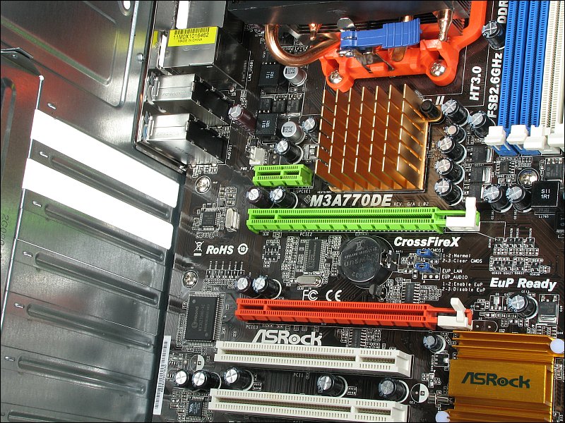
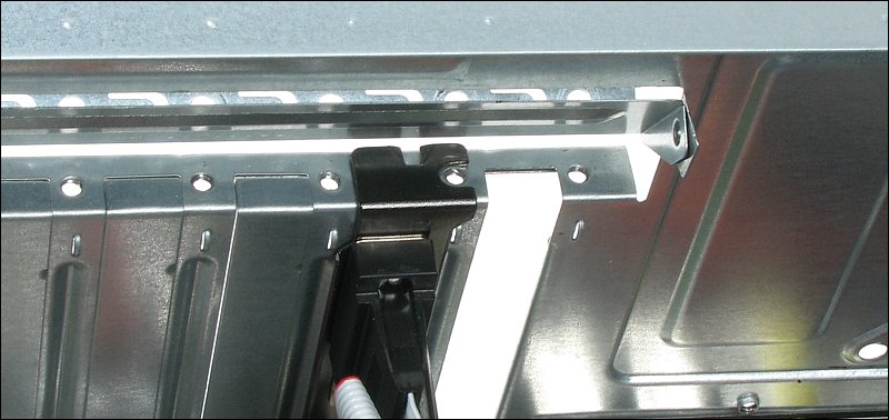
 Below, the long green slot is the PCI-E slot. That's where we'll install the graphics card. Although it's not important, the card is a Radeon HD 5570. Before you try to install the card, you will have to remove the corresponding expansion slot cover. If you're not sure which one it is, position the card over the slot and see which cover needs to be removed. If there is anything over the top of the screw hole or clamp for the backplate for the card, it will have to be removed or moved out of the way while you insert the card. Also make sure that the sliding clip (if it has one) on the back end of the PCI-E slot is as fat to the front of the case as possible.
 Insert the card into the slot and push it down until it's fully seated. The top of the rear bracket should touch the case and the slot in the bracket should align with the screw hole.
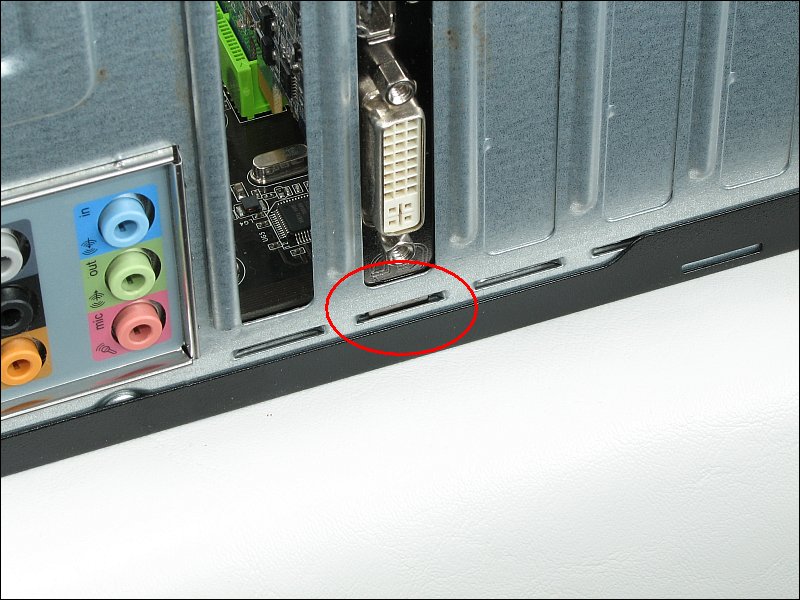
 If the back end of the card won't go down as easily as it should, it's possible that the bottom of the back plate of the card is catching on the opening under the main opening for the expansion slot. Here, it's too small to be a problem but when the height of that extra opening is a bit greater, the plate can and will get caught. Simply push in on it while pushing the card down in the slot.
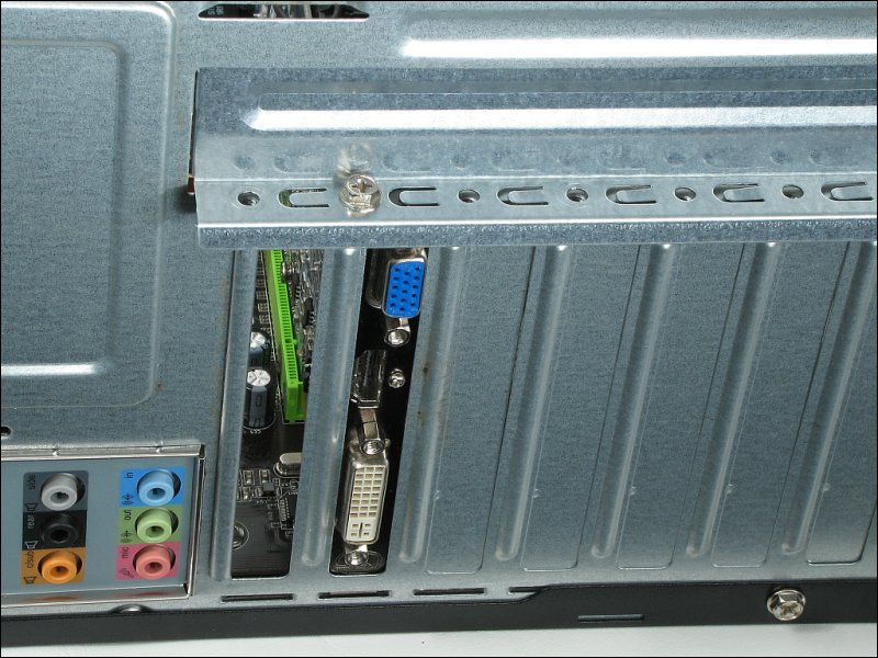
 When everything is down as it should be, install a screw (or clamp the card down with whatever your case provides).
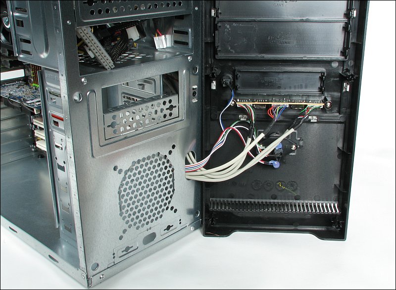
Virtually all computer cases need forced-air cooling. For low power computers, the power supply fan draws enough air through the case to keep it cool. For today's computers with more powerful processors, extreme graphics cards and high multiple conventional hard drives, you need additional cooling. The most common fan setup has one fan pulling fresh air into the front of the case and a second one forcing warm air out of the rear of the case. Here you can see the front grill of the case. The front panel has been removed.
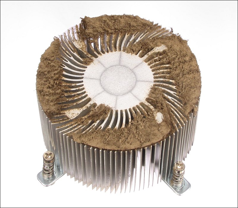
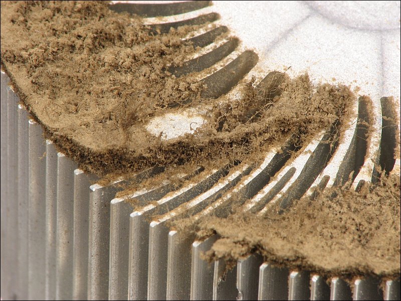
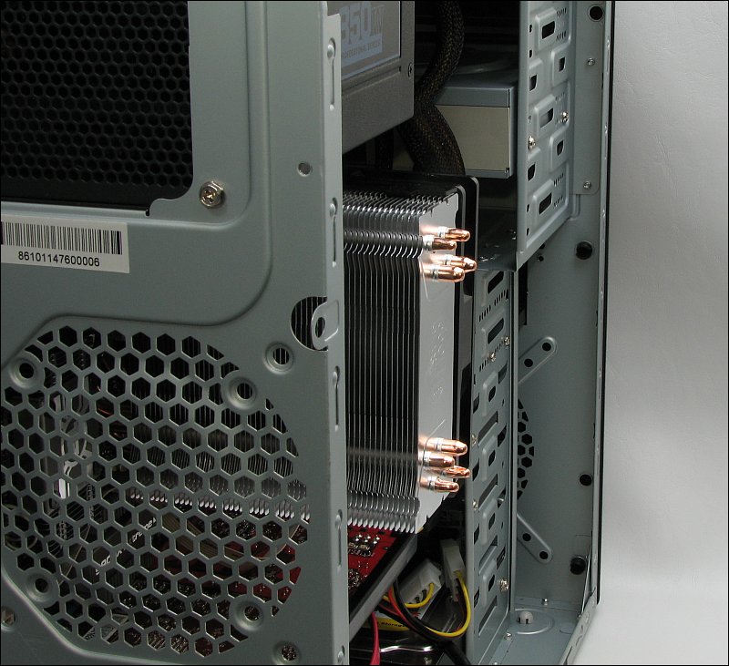
 Having fans pulling air through the case is necessary for most computers but you should realize that this essentially makes them vacuum cleaners. For most computers, they're pulling dust into the computer 24 hours a day. If you have a lot of air flow (multiple high-performance fans), you may want to buy a case that allows you to have an air filter. If you don't have an air filter, it may be necessary to periodically clean the heatsinks on the microprocessor and on the graphics card (if it has a fan on its heatsink). If you don't clean them, it's possible that dust will build up to a point to where there will be very limited airflow through the heatsinks and the processors (CPU or GPU) will overheat and possibly fail. If the owner of the computer is a heavy smoker, the problem is much worse because the smoke gets pulled through the computer making the dust very sticky. Generally, the dust can be blown out with a compressed gas duster or an air compressor (preferably one with a water trap). However, when tobacco smoke is involved, the heatsinks have to be removed and either replaced or cleaned in solvent. The following heatsink shows about shows a CPU heatsink that's almost completely blocked. Most of the areas that ate not blocked are areas that were occupied by the fan struts and frame.
 Previously, it was stated that the front fan generally pulls air into the case. Of late, I've been installing them to push air out of the case. Actually, all of the fans but one are installed forcing air out of the case. That allows the one forcing air into the case to have a filter on it to keep the case clean. On the one I use the most, I have an external box with a high volume fan pulling air through a 24"x30" furnace type air filter then forcing that clean air through a dryer's exhaust hose into the bottom of the case of the computer. It's extreme but it's been in use for over a year and there is no accumulation of dust on any of the internal components. Since this is in my workshop and the shop is often very dusty, that's a significant accomplishment. For most home installations, the solutions are much simpler. There are cases that have filter panels in them (like those used for window air conditioners) that are easy to remove and clean. The fan here works to force air out of the front but it's located in front of the hard drive bays so that it will help keep the hard drives cool also. Many of the newer drives ('green' drives) produce very little heat and don't really require forced air cooling. Many of the older, high performance drives (like the original Raptor drives) produced quite a bit of heat and needed the fan to keep them at acceptable operating temperatures. If you don't have a fan in front of the hard drives, you should monitor the temperature of the hard drives when you begin using the computer. Install all of the case covers and use it for about an hour. Remove the cover and check the temperature of the drive. if it's too hot to hold your hand on for 15 seconds, it needs a fan to help keep it cool. There are various applications that will tell you the temperature of the hard drive (drives with S.M.A.R.T.). One such application is PC Wizard. It's a very useful piece of software that can also tell you many things about your computer (or a computer you're repairing).
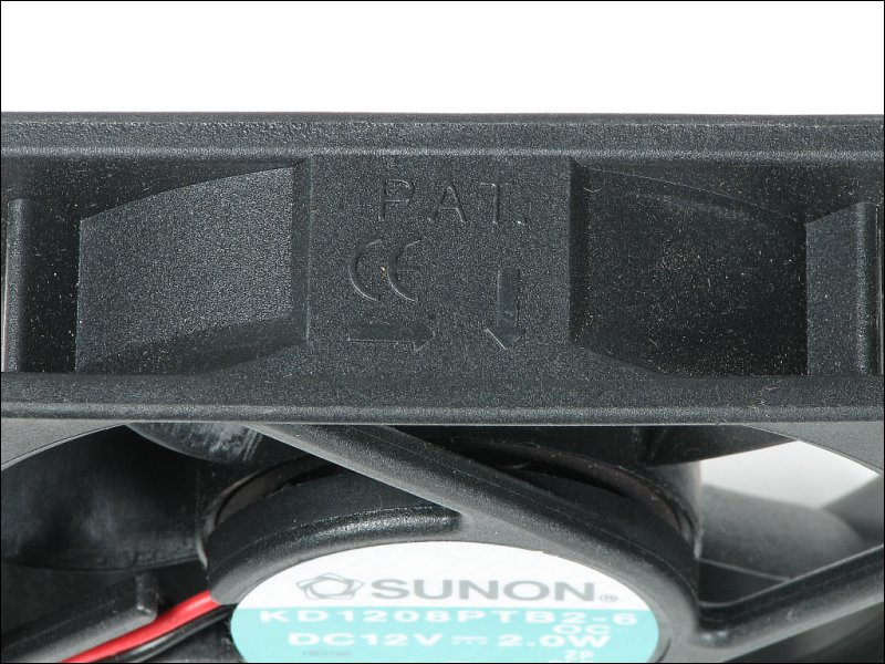
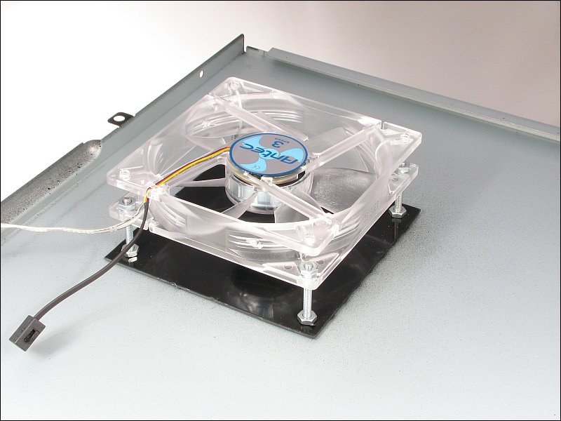
 If you don't know which direction a fan blows when it's in operation, for 12v DC fans it's always through the struts (strut-side discharge). Most fans are marked to show you the direction the blades turn as well as the direction of air flow. You can see one example below. Notice that the arrow faces to the side of the fan with the struts.
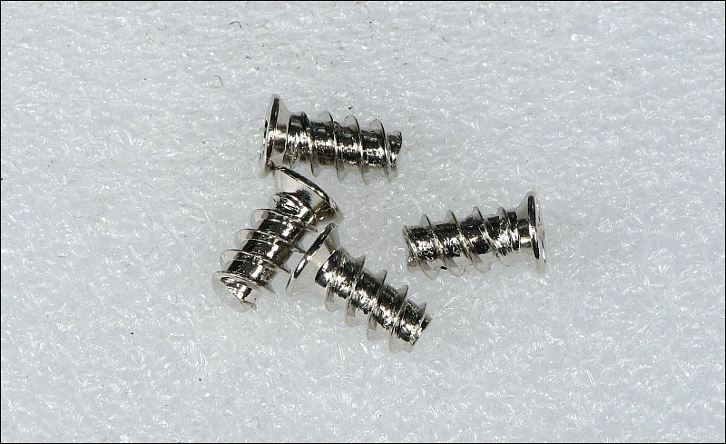
 Fan manufacturers generally provide the mounting hardware for their products. The screws they provide have a very aggressive thread pitch which means that they screw in with just a few turns. These are much better than the old way with machine screws and nuts.
 If you use a filter of some sort, you'll need to confirm that the filtering system is working as it should. You'll need to check the airflow at several points. They make smoke-pens for this but they're expensive. I've found that using incense sticks (the long ones) works well enough. With a stick burning, make sure that all openings, fans and seams are blowing the smoke away from the computer except the one with the filter. If you place it near any seam in the computer's case and the smoke goes towards the case, the airflow is wrong there and you need to fix it. If you don't, that's a point where dust will enter the system. This is very important... You must have a fan forcing air into the case and you must make sure that the power supply is forcing air out of the case. The flow through the power supply should be equal or greater when the side cover is removed, compared to when the side cover in in place and the computer is sealed up. If you have no fan forcing air into the case or it's not forcing enough air into the case, the flow through the power supply will be reduced and the power supply could overheat and fail prematurely. When selecting a fan for your case (or any computer related application), you will have a choice between several types of bearings. The most common are sleeve bearings (brass bushings) and ball bearings. Some fans are also available with one sleeve and one ball bearing. Initially, the sleeve bearings are almost always quieter than ball bearings but the difference is generally insignificant because neither is really noisy and the sound of air rushing through the fan generally drowns out the sound produced by the bearings. The major difference between the two types of bearings is the service life of the fan. Ball bearing fans can run for years, non-stop without failing. I have some that have been through several computer cases and will likely go into the next computer I build. Sleeve bearing fans 'can' last a long time but many times, cheap/poor quality lubricants and poor tolerances in the fans makes them fail after a couple of years. The first signs that the fan is failing is a sort of a growl. This is the axle of the fan's rotor wobbling in the bearing. Many times, the fan can be disassembled (simply remove the split-ring retainer), the old lubricants 'completely' removed and then re-lubricated. If a good quality lubricant is used, the fan can function for longer than it did originally. When selecting fans, you will also have to decide how much air you want to move with it. Generally, there is a trade-off here. If you want to move more air, you will have to tolerate more noise. The air flow is specified as a number of cubic feet per minute (CFM). Higher CFM = more air flow. Also, in general, a larger fan can move as much air as a smaller fan with less noise. A small fan will have to spin faster and have a more aggressive blade design to equal the air flow of a larger fan. If you have a choice of an 80mm or a 120mm fan for a particular location in your case, using the 120mm option will produce less noise (all else being equal).
Top Fans:
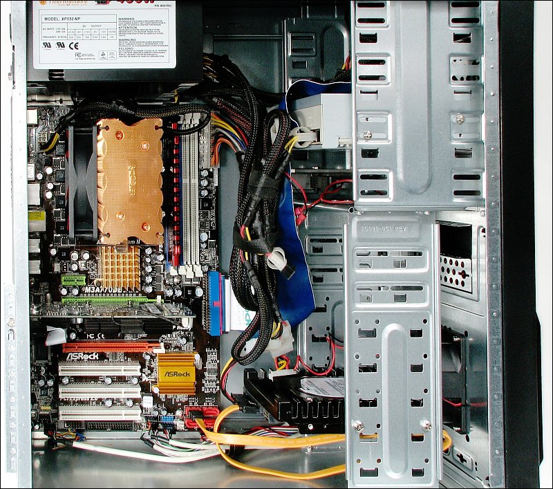
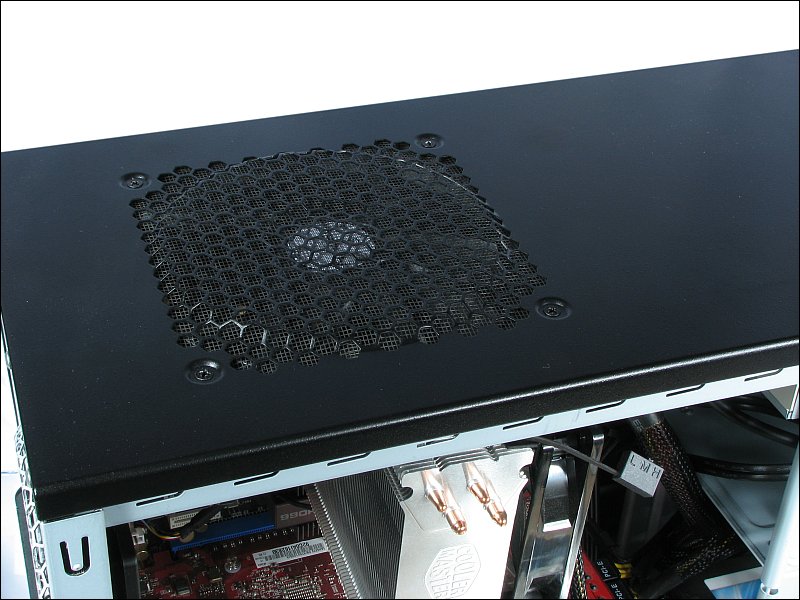 In the photos above and below, you can see that there are cables that are not tied up like the rest of the cables. Here, they are the switches for the 3-speed fans. If you don't control where wires like these are allowed to move, they can easily get caught in one of the fans. If the wires prevent the fans from turning, it could cause damage to the fan or to the device that the fan was intended to cool.

CPU Coolers and Clearance:
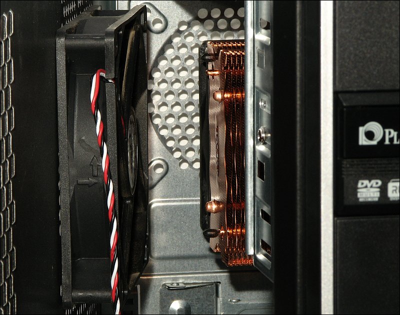 In the next two photos, you can see that I was not so lucky. The first photo shows that the top of the cooler (Coolermaster Hyper 212 EVO) is out too far and makes it impossible to close up the computer. The options are changing the cooler or the case.

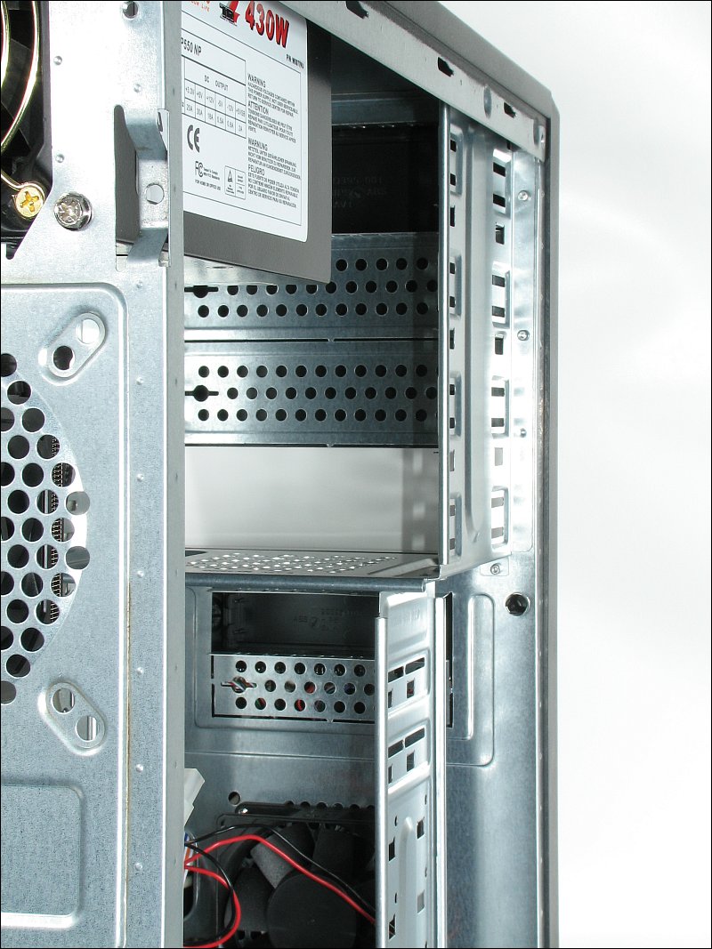
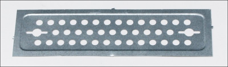
The physical installation for the hard drive wasn't shown because you simply slide it into a slot that it fits in and install the screws. The optical drive is almost as simple but you have to do a bit more work. In the next photo, you're looking into the case from the back and you can see that one of the front access covers has been removed from the case. If you look just above the open slot, you can see that there are metal panels behind the access slots. Originally, there was one behind the one that's currently open but it was (obviously) removed. The top slot didn't have one and that's where they expect you to install the drive but I've found that they get too hot when mounted at the top (or when two drives are mounted directly on top of one another. When mounted lower, they run cooler. To remove the plastic covers, you simply push it out from behind. If there is a metal shield behind the plastic panel, use a screwdriver to push the plastic panel out through one of the holes (from the inside of the case). To get the metal shield off, you typically have to bend them until the metal breaks. In some cases, there are screws that you have to remove.
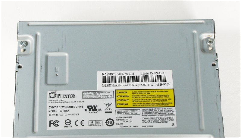
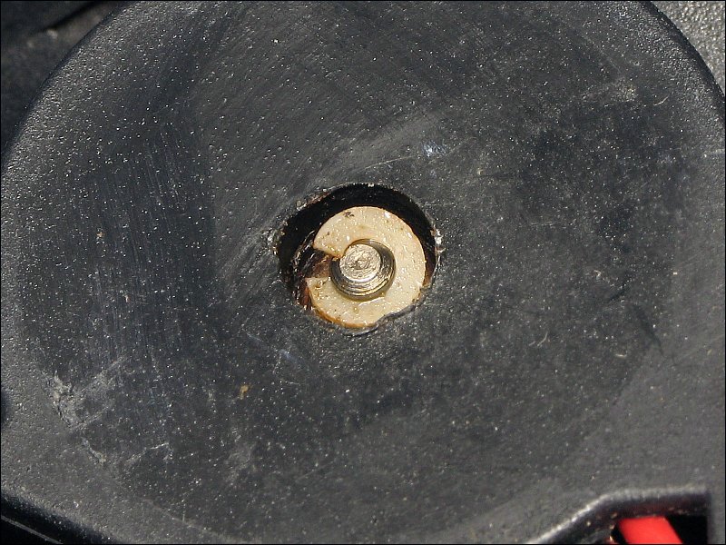
 For those who burn a lot of discs, I'd recommend mounting a fan under the drive to help keep it cool. Under most drives, there is at least one rectangular indention. Sometimes you can see a bit of soft white or pink material being pushed out of a hole in it. This is where the heat is sunk to the drive enclosure. This area gets hot when burning discs and gets very hot when you burn several discs in a row. If you burn a lot of discs, this is the are you need to cool. A small fan is all that is needed.
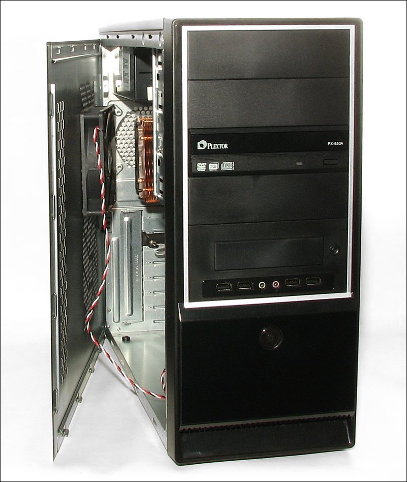
The Assembled Computer:
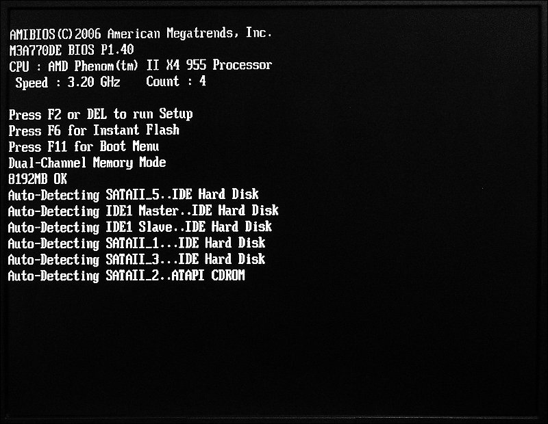
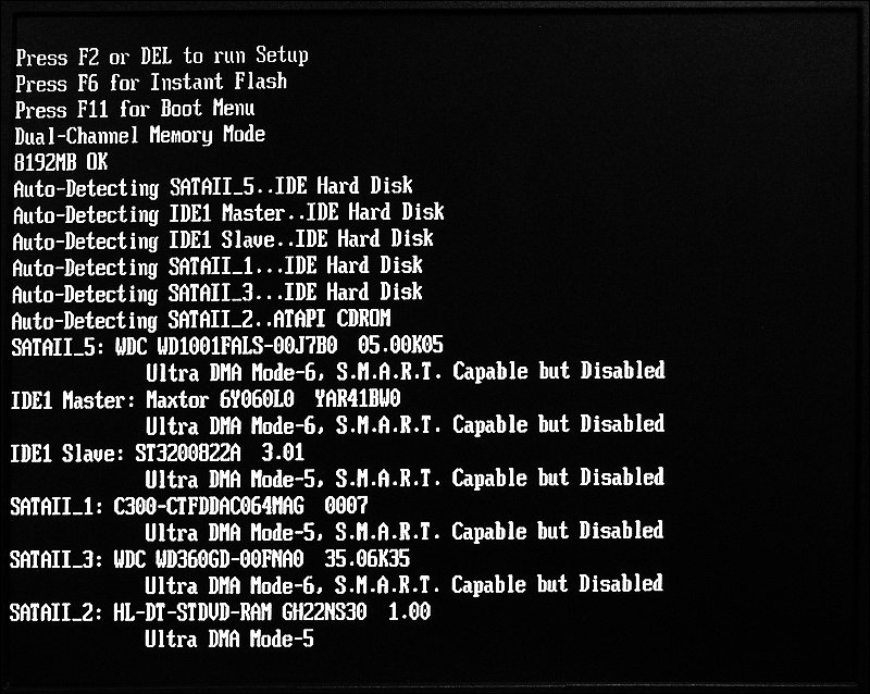
The first time you turn the newly built computer on, you should see a black screen with white text that gives information about the system (memory, graphics, hard drives, optical drives...). Much of it will scroll off of the screen before you can read it. Many motherboards will display a splash screen with their logo or showing some of their features. There is generally an option, while booting, to switch the splash screen off, allowing you to see the boot procedure. If the boot process is so fast that you don't have time to switch screens, you can disable the splash screen in the BIOS. To enter the BIOS, you generally have to hit one specific key to enter the setup mode. The key you have to hit is given on the first screen that displayed. After the splash screen is disabled, you can pause the boot sequency by hitting the pause/break button on your keyboard. The following two images show you the initial part of the boot sequence from a M3A770DE motherboard. Your display will be different (even if you have the same board). What's important is that you not expect to have anything resembling a Windows interface. That will only be available if you have an EUFI BIOS or when you begin installing your operating system.
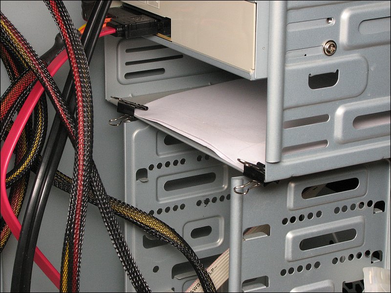
 If the system doesn't boot and gives you a series of beeps (this is why you need a speaker connected to the motherboard, initially), you will need to look up the error codes on the owner's manual. If there are no beeps, you'll disconnect all non-essential components from the system (all that's needed are the power supply connections, a video card (integrated graphics adapter if no discrete card is installed - but you have to have some type of video output device), the CPU and at least one memory module. If it still won't boot, you'll have to do a bit more in-depth troubleshooting. The Troubleshooting page of this site has many of the common faults. It's possible to have a DOA piece of equipment. The motherboard or the power supply are the most likely culprits. The memory and CPU have likely been tested thoroughly before they were packaged. Before you get angry and post nasty comments about getting a DOA product, check everything that you can (make sure that all connectors are properly seated, remove and re-seat the memory modules...). If nothing resolves the problem (including the items suggested on the troubleshooting page), contact the tech support for the products or find a forum for the motherboard or CPU. They are likely to be the most helpful in getting the problem resolved. If it is determined that you indeed have a DOA component and you have to return it, you can expect to have to pay return shipping. On upcoming pages, you'll see that you have to install drivers and software. It's likely that you'll need those discs at a later date. To keep up with them, clip them to something inside the case. If you only have one or two discs, you can clip them as shown below. If you have more, place them in a Ziploc bag (or anything similar) and clip the bag in place. When doing this, be sure that the clip only applies pressure to the paper/plastic and not to the discs.
Filters were mentioned previously on this page. This section will provide a bit more information to help you keep your system clean and working properly. Some cases include filters on their fan mounting locations but most don't provide filters for every fan mounting location. For those locations with filters, you will have the fan pulling air from outside the case, through the filter. For those with no filters, you will have the fan pulling air from inside the case and exhausting it from the case. If you have a fan pulling air into the case without a filter, it will pull dust inside the case and defeat the purpose of having filters on the other fans. As was previously mentioned, you have to be careful not to have too much flow from inside the case. If you do, you risk reducing the air flow through the power supply which could cause it to fail. Many power supplies have very slow turning fans (to reduce noise) and can't compete with more powerful fans. In one instance, an Antec Three Hundred case was used. There was one top fan, one rear fan (both exhausting air), two front fans (drawing in fresh air through filters) and one side fan that was intended to cool the graphics cards. Since there was no side fan filter, the side fan could not be used to pull air into the case so it was installed as an exhaust fan. With this setup (3 exhaust fans and 2 intake fans) the airflow through the power supply was FAR less than it was without the exhaust fans or if the side cover was off of the case. Since all of the case fans had speed controls (L, M, H), I attempted to balance the flow by setting the intake fans to high and the exhaust fans to low. This helped but not enough to completely restore the flow through the power supply. The only way to restore the airflow through the supply was to eliminate the side fan (or at least prevent it from moving air through the fan grill. The fan was needed so it was used in a different way. This particular system had graphics cards without fan shrouds which meant that they didn't exhaust the air from the heatsinks on the cards. The air didn't move far in the case and tended to make the area around the cards hot as the hot air was basically recycled. To increase the air flow in the area, the side fan was used to draw air from a cooler part of the case and force it into the area around the graphics cards (shown HERE). In the photo below, you can see that the side vent/grill has been blocked off and the fan has been mounted so that it's about 1/2" off of the side of the cover. This is plenty of space from which the fan can pull air. Adding the fan to that location and using it as described/shown reduced the temperature of the cards by about 9�C.
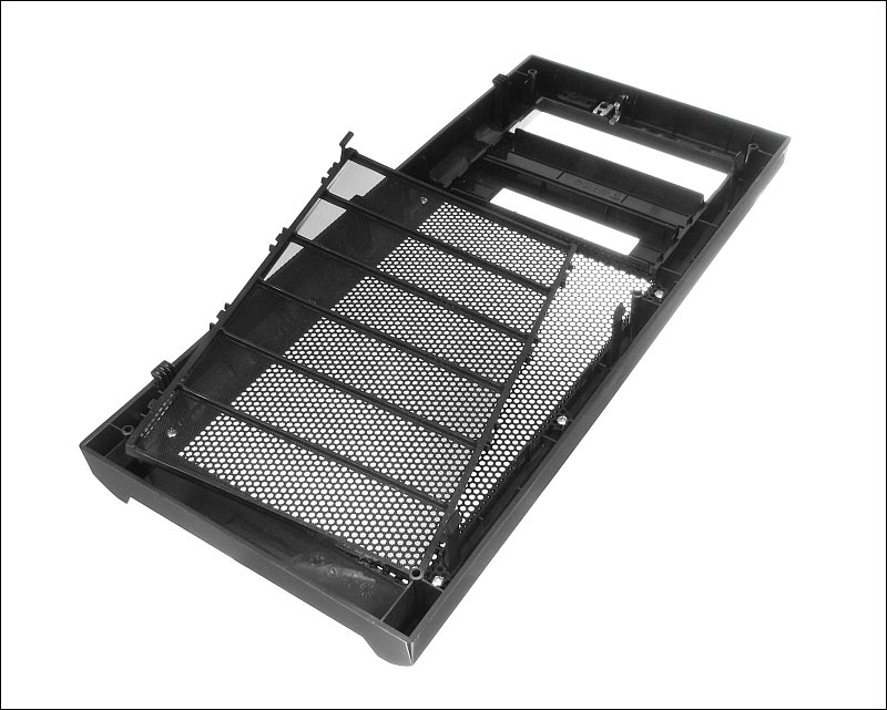
 When attempting to balance the airflow through the case, you may not be able to tell precisely how the airflow changes from one setup to another. As was previously stated, smoke (incense sticks is one source, after blowing out the flame) allows you to see how air is flowing. For the intakes, it works very well. Sometimes, on the exhaust fans (particularly those with minimal airflow) it can be confusing. For exhaust fans, a strip cut from the thin plastic bags (like those you'd get from Wal-Mart) can better indicate the volume of exhaust airflow. Cut a strip about 1/2" wide and about 2-3" long and fasten it to the case so that the strip lays in front of the exhaust fan. For the Antec case mentioned above, with all of the fans on high (two intake and two exhaust) and the strip in front of the power supply exhaust, the strip would barely move. It essentially laid flat against the power supply exhaust grill. When the case was opened, the strip blew out to about a 45� angle. When the two exhaust fans were set to low instead of high, the strip dropped just a bit but the airflow through the supply was easily acceptable. Not many fans have speed controls. Some cases include speed controls but often there is only one control for all fans. To balance the flow through the case, you will often need a control for each fan. There are fan controllers that will allow you to vary the speed for each fan. These can be helpful (required) to balanced the airflow if you have no other way to control the speed of the fans. When you have a case that has filters (or if you build a filtered air supply, as was mentioned previously on this page), be sure to check the filters regularly. If you leave the computer on 24/7, the filters will get dirty more quickly. If you have pets or live in a dusty environment, the filters will require more frequent cleaning. Many of the case filters are the washable types. You generally wash them under the faucet. Wash them so that the water flows through the filter in the opposite direction of the air when they are in the case. If there is a smoker in the house, the filters will likely get sticky and will require a bit of soap (like dish-washing soap) to get them clean. After washing the filters, dry them thoroughly before reinstalling them. The image below shows the front panel of the Antec Three Hundred case with it's washable filter removed.
|
|
| Contact Me: babin_perry@yahoo.com | |
|
Perry Babin 2005 - Present All Rights Reserved
|