Airbag Warning:
An old-style test light that uses an incandescent lamp as an indicator can (read: will) set off a supplemental restraint system if the wrong wires are probed. These wires are generally (but NOT always) marked with yellow loom or tape and likely have yellow connector housings. If you probe one of these wires (which may be in virtually ANY factory wiring harness anywhere in the vehicle), and set off a single airbag, you may easily cause THOUSANDS of dollars in damage. If you hit the wrong sensor wire and trigger ALL of the airbags, there may be enough damage that the vehicle may be totalled from the cost to replace the bags and the affected trim panels. Some airbag systems destroy the entire dash, the door panels and even parts of the seats when they deploy. This page shows how to use a test light to test for blown fuses in the aftermarket audio system that you installed (or are going to install). If someone asks you to work on a car with airbags, and you don't know what you're doing, DON'T do the install. If you're going to install a system in your vehicle and are going to be probing wires of which you don't know their precise function, use a multi-meter to find the appropriate wire. As a final note, disconnecting the battery in the vehicle does not necessarily remove the chance of the SRS deploying. Some systems have backup supplies which are designed to allow the system to work properly even if the battery is destroyed in the accident.
A test light is, when properly used, one of the best and quickest pieces of test equipment available for troubleshooting 12 volt power systems. It's especially good for times when there are only two voltages, battery voltage and no voltage. For example, if you're checking to see if you have 12v on the B+ and remote terminals, the test light will immediately tell you if voltage is present or not.
Test Light Types:
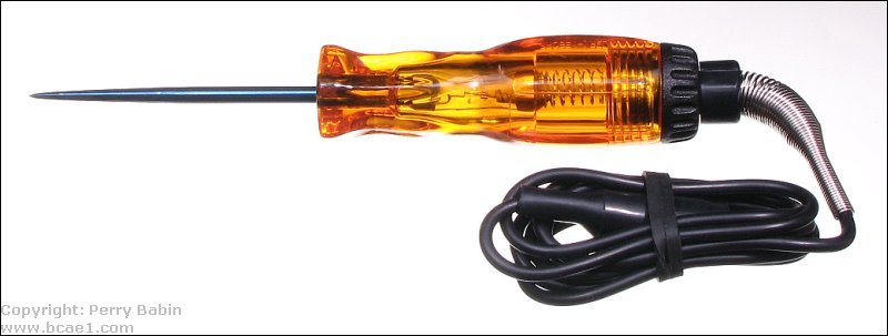
There are many different types of test lights. The older style had an incandescent lamp and the point being probed supplied the current to make the lamp light up. This current draw by the internal lamp could cause damage to some circuits. Now there are test lights that draw virtually no current. The ones that draw the least will typically require a power source. They can have an internal battery (like a multimeter) or plug into the power port (cigarette lighter). There are still others that operate much like the old style but instead of an incandescent lamp, they use an LED. The LED will draw much less current than the incandescent lamp so it's less likely to damage sensitive circuits. These and the ones that require a power source are often deemed 'computer safe'. This refers to the computers and various control modules used in newer vehicles. The following test light is a simple test light. It requires no additional power and uses an LED instead of an incandescent lamp.
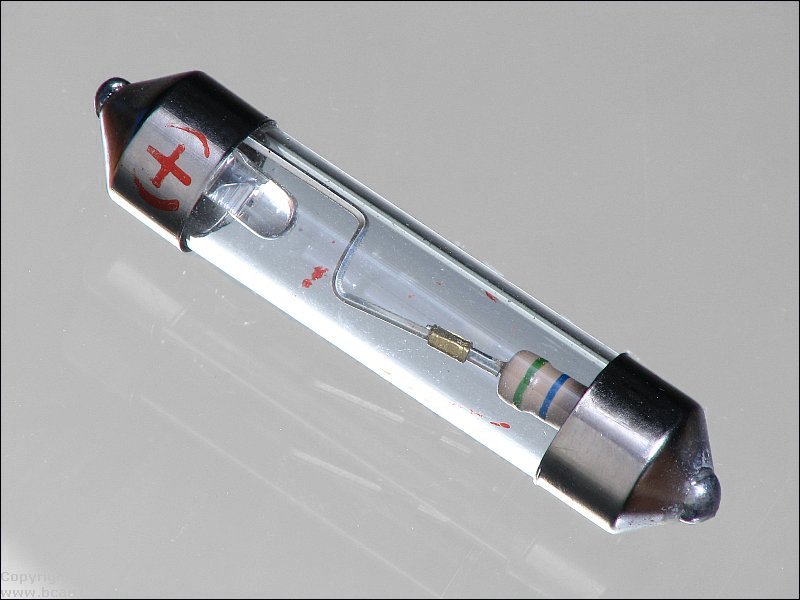
The test light above doesn't look any different than one with an incandescent lamp. If you need to determine what type of light source a test light uses, you can partially disassemble it and determine what it uses. The following is the LED module that makes up the light source. The glass tube is similar to standard incandescent lamps in size but instead of having a filament, it has a resistor and an LED. If you look at the left end of the module, you can see that there is a '+' sign. LEDs are polarity sensitive so you have to install the module with the plus sign towards the probe of the test light. In most instances, the test light with an LED light source will not light up if you install the module backwards. The module, however, has two colors. When the probe is more positive than the clip terminal (ground, generally), the LED will be red. When the clip is connected to a point where the voltage is higher than the point that the probe is on, the LED will light up green.
Test lights that use incandescent lamps can draw significant current. I have one that uses a Sylvania type 1893 lamp. That lamp is rated for 0.33 amps of current. That's enough to damage some of the remote output drivers in head units. One of the most popular test lights from Snap-On, uses the 205120 lamp. Its current rating is 0.05 amps. That's much safer than the one that draws 0.33 amps.
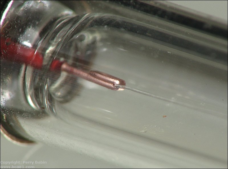
If your test light has a light source similar to this but you're not sure what it is, you can identify the ones that are incandescent by looking for the filament and the crimped pieces of metal that hold them in place.
Input Voltage:
The test light will light when there is a sufficient difference of potential between the point of the light and the alligator clip on the other end of the ground wire. One drawback to using a test light, especially one that uses an LED, is that you can't really tell what voltage you have. The test light above will be relatively bright on only about 4v. With an incandescent light, it's easy to determine when you have approximately 12v and when you have significantly less because the intensity of the light is significantly different.
A Safe Alternative:
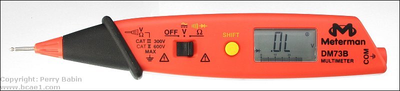
For those who want to use a test light because it's easier to see and it's not necessary to look away from the connector to look at a multi-meter's display, the next meter may be a suitable alternative. These are made by several manufacturers and bridge the gap between a meter and a test light. This one has the advantage to give an actual voltage reading. It functions exactly like a standard multimeter, being able to measure resistance and check diodes/semiconductors. Like any other multimeter, this is computer and airbag safe.
Multimeter vs Test Light:
The following shows the equivalent between the reading on a digital multimeter and a test light. You can see that the wires that have 12-14.5 volts on them also light the test light. You can (and probably should) use a voltmeter for troubleshooting. If you do, the meter will read approximately 12-12.5 volts with the engine off and will read between 13.5 and 14.5 with the engine running. If you're not probing anything other than the wires going into the radio or the amplifier, the test light is safe. If you're testing the voltage in any other connector under the dash, you absolutely MUST use a digital multimeter. You'll notice the the meter grounds are connected to a shiny, bare piece of metal. This is also necessary for the test light but the test light's ground was omitted for clarity.
----- Critically Important -----
Adobe has deemed that the Flash content on web pages is too risky to be used by the general internet user. For virtually all modern browsers, support for Flash was eliminated on 1-1-2021. This means that those browsers will not display any of the interactive Flash demos/calculators/graphics on this (or any other) site.
The simplest (not the best) fix, for now, is to download the Ruffle extension for your browser. It will render the Flash files where they were previously blocked. In some browsers, you will have to click on the big 'play' button to make the Flash applets/graphics visible.
An alternative to Ruffle for viewing Flash content is to use an alternative browser like the older, portable version of Chrome (chromium), an older version of Safari for Windows or one of several other browsers. More information on Flash capable browsers can be found HERE. It's not quite as simple as Ruffle but anyone even moderately familiar with the Windows Control Panel and installation of software can use Flash as it was intended.
Testing Examples
NOTE:
In the following examples, the ground wires for the test lights were omitted for clarity. Test lights with light bulbs will not work without the ground wire being connected.
Amplifiers:
In the lower right of the diagram below, you will see the legend which shows which test light is on and which is off. You will see that all connections to the battery side of the fuses have 12 volts on them. You can also see that there are 2 fuses. One of the fuses is blown. you can see that the light on the amplifier side of the good fuse is lit and the light on the amp side of the blown fuse is NOT lit.
In the diagram below, the remote output is off. Both amplifiers are off. Notice that the test lights on the amplifiers' remote terminals are not lit. The test lights on the battery terminals are lit. These two examples should give you an idea of how to troubleshoot with a test light. If you know which terminals or wires should have power, you can use a test light to quickly find many of the problems that you'll encounter.
Note:
The wire colors in the following diagrams are generic wire colors. You MUST consult the owner's manual for your head unit for the proper wire color codes.
Head Units:
In the following diagrams, you'll see when voltage is present on each of the power and control wires. If you're new to car audio, read the head unit page for a better description of the function of each wire connection.
In this first diagram, you can see:
The ignition switch is off.
The memory wire has 12 volts (battery voltage).
The ground wire shows that there is no voltage present. This is because it is connected to ground (obviously). If you ever probe a ground connection, and there is voltage present, the connection to ground is bad. Remember that the ground clips for all of these test lights are connected to a known good ground.
There is no voltage on the ignition, remote or power antenna wires. Keep in mind that some head units have a single wire which is designed to control the power antenna. It would operate as the 'remote' wire in this diagram (it will have 12 volts on it whenever the head unit is in operation).
This diagram shows:
The ignition is ON.
The head unit is OFF.
The remote and power antenna wires have no voltage present.These wires will never have voltage on them when the head unit is switched off or when the ignition is switched off. If voltage is present on either of the blue wires when the head unit is off, the head unit is damaged.
This diagram shows:
The ignition is ON.
The head unit is ON and the radio is playing.
The remote and the power antenna wires have voltage on them. If the amplifier is connected to the remote wire, the amplifier(s) will be on. If the power antenna wire is connected to the control lead of the power antenna, the power antenna will be up.
In this diagram:
The ignition is ON.
The head unit is on and playing a CD.
The remote lead has power and the amplifiers will be ON.
The power antenna wire has no voltage on it and the power antenna will be down. If the amplifiers were connected to this wire (which is specifically designed to control a power antenna), the amplifiers will switch off when a CD is inserted.
Testing the light:
With any test equipment, you should confirm that it's in good working order before you begin testing. For a multimeter, the most common test is to set the meter to ohms and confirm that the meter reads 0 ohms (or VERY near 0 ohms) when the metal parts of the probes are touched together. For a test light, you have to have a voltage source. Connect the test light's ground clip to a good ground and touch it to a point where you believe that there is 12v. If you're in the rear of the vehicle, you can touch the main power wire where it goes into the distribution block. If the light doesn't light up, check the light by connecting it directly across the battery. Initially, make sure that you have the ground clip on the negative battery terminal. If you touch the probe to the positive terminal, the test light should light up. If it doesn't and the battery is not completely dead, the test light isn't working properly. For a test light that uses an LED, you may want to also test it with reverse polarity also. Some test lights light up a different color when the polarity is reversed.
Brightness of test light:
After you have used the same test light for a while, you will be able to detect a low voltage condition by the brightness of the lamp. When driving an amplifier at high power, the test light (which would be connected to the amplifier's positive and negative terminals) may indicate whether or not the power wire (that delivers power to the amplifiers) is large enough by dimming more than expected. If you see that the light is dimming significantly, connect the test light to the battery. If the light dims less at the battery, the power wire for your amplifiers may need to be upgraded. Keep in mind that it will always dim slightly more at the amplifiers but there shouldn't be much difference between the amplifier's power terminals and the battery.
This site was started for pages/information that didn't fit well on my other sites. It includes topics from backing up computer files to small engine repair to 3D graphics software to basic information on diabetes.
This site introduces you to macro photography. Macro photography is nothing more than the photography of small objects. It can take quite a while to understand the limitations associated with this type of photography. Without help, people will struggle to get good images. Understanding what's possible and what's not possible makes the task much easier. If you need to photograph relatively small objects (6" in height/width down to a few thousandths of an inch), this site will help.
If you're interested in air rifles, this site will introduce you to the types of rifles available and many of the things you'll need to know to shoot accurately. It also touches on field target competition. There are links to some of the better sites and forums as well as a collection of interactive demos.
This site helps anyone new to computers and anyone with a basic understanding of computers with a desire to learn more about the internal components of a computer. If you have a computer that you'd like to upgrade but don't know where to start, this is a good site for you.
This site is for those who want to begin racing karts but don't fully understand how the various parts work. It's mostly interactive demos that show how the various parts of the kart work.
You should remember:
1.The indicator in an incandescent lamp based test light will light when there is a sufficient difference of potential (voltage) between the test light's probe and the test light's ground clip.
2.The lamp in a test light can give you an indication of a low voltage situation or a voltage drop in a circuit.
Click HERE to visit a friend's new car audio tech site.

 An old-style test light that uses an incandescent lamp as an indicator can (read: will) set off a supplemental restraint system if the wrong wires are probed. These wires are generally (but NOT always) marked with yellow loom or tape and likely have yellow connector housings. If you probe one of these wires (which may be in virtually ANY factory wiring harness anywhere in the vehicle), and set off a single airbag, you may easily cause THOUSANDS of dollars in damage. If you hit the wrong sensor wire and trigger ALL of the airbags, there may be enough damage that the vehicle may be totalled from the cost to replace the bags and the affected trim panels. Some airbag systems destroy the entire dash, the door panels and even parts of the seats when they deploy. This page shows how to use a test light to test for blown fuses in the aftermarket audio system that you installed (or are going to install). If someone asks you to work on a car with airbags, and you don't know what you're doing, DON'T do the install. If you're going to install a system in your vehicle and are going to be probing wires of which you don't know their precise function, use a multi-meter to find the appropriate wire. As a final note, disconnecting the battery in the vehicle does not necessarily remove the chance of the SRS deploying. Some systems have backup supplies which are designed to allow the system to work properly even if the battery is destroyed in the accident.