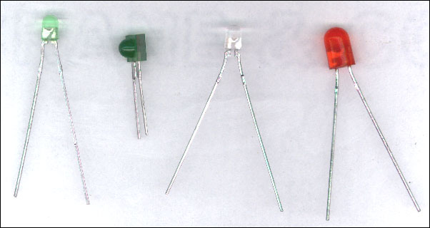
An LED is a special semiconductor which emits light when current is passed through it. There are many different physical styles. The emitted color spectrum is usually very narrow. It can generally be specified as a specific wavelength in the electromagnetic spectrum. The emitted color selection is somewhat limited. The most commonly available colors are red, green, amber, yellow, blue and white. The red, green, yellow and amber have a working voltage of approximately 1.8 volts. You can refer to the data sheet for each LED to find the exact value. The actual working voltage is determined by the breakdown voltage of the particular semiconductor material.
Colored LEDs:
Multi-color LEDs and some white LEDs have multiple dies (the semiconductor material that produces the light). The color can be changed by illuminating the dies at various levels. White LEDs are also sometimes blue LEDs with added phosphors to make them emit white light.
LED Lenses:
LEDs often share a common shape. The plastic housing is shaped to produce a specific viewing angle. For any given LED die, the light pattern can be shaped to provide a very tight beam or a wide beam by changing the shape of the lens (the plastic housing, in front of the die).
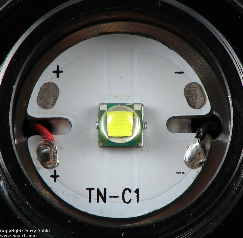
Most LEDs are designed for very low power consumption and low output (light output). Even though the LEDs sold as super-bright LEDs may seem bright if you look directly at them, they are still low power LEDs. The 'super-bright' LEDs are typically in a standard LED package and require no heatsink to operate at the recommended current. LEDs that are really bright can be seen for miles. These are typically used in flashlights. One example is the Cree XM-L LED (datasheet HERE). The following image shows the XM-L LED in a ThruNight Catapult V2. The LED is soldered to a heatspreader. This increases the effective surface area of the LED to promote greater thermal transfer. The heatspreader is flat against a large piece of aluminum that serves as a heatsink. Between the aluminum, there is a layer of thermal/heatsink compound. When the reflector assembly is screwed on, it presses the heatspreader against the heatsink. All of this is required for a high power LED to operate at full power.
For more information or to see what high power LEDs can do, search for Catapult XM-L beamshot with Google or on Youtube. For more information on high-end flashlights, visit the Flashlight page of this site.
LED Drive Current:
When using an LED in a circuit, the exact working voltage is not extremely important. The most important thing is the current flow through the LED. The current through the diode must be limited by a series resistor. An LED has a specified maximum continuous current rating. Most LEDs can pass 20 milliamps continuously without damage but it is not necessary to use the maximum rated current. An LED will light with much less current. The difference between high current and low current will be the brightness of the LED. To decide what resistor value is needed, you subtract the working (forward) voltage from the power supply voltage and divide that number by the desired current flow.
Working voltage (Vf)=1.8 volts
Desired current flow=15ma (.015 amps)
Power supply voltage=12 volts
12-1.8=10.2
10.2/.015=680 ohms
A 680 ohm resistor will limit the current to a safe level although I would probably use a 1000 ohm in a vehicle because the charging system voltage would be higher than 12 volts. Any resistor between 680 and 4700 ohms would probably work fine. Choose a resistor with a power rating greater than or equal to the power dissipation given by the calculator above.
----- Critically Important -----
Flash graphics viewing/use alternatives:
Flash support by most modern browsers has been dropped but that's not the end of the line for Flash.
There is no practical alternative to Flash for the interactive demos/applets/graphics on this site.. Especially when there are alternatives, some simple, some good, some...
Ruffle is chosen by most because they can't imagine using anything but their preferred browser. It works. It's OK but not great. The Flash graphics won't look as they're supposed to but it, generally, works.
The #1 preferred (by me) way to view the site and the Flash graphics is with the Chromium Portable browser and the installation of the older (no time-out) Flash Player files. This was incredibly simple when people knew computers but not today when people only know how to work with their phones.
The Flash Browser is a good option but it's so stripped down that it makes it somewhat difficult to use.
The Maxthon browsers are an option. The v4.95 is the easiest (install and use). V5.3.8 and 6.1.0 require (very) slightly more effort (very).
The Chromium and Maxthon browsers on the page above are 'portable' browsers. They are not installed into your system. They are simply made available for use on your computer. They can be carried around on a Flash drive and used on any computer.
----- Critically Important -----
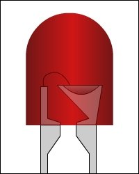
The diagram below shows the parts of an LED.
Click HERE to open this graphic in a new tab. Right-click to zoom. Left-click to drag.
You must also know that an led has polarity. This means that the positive and negative terminals must be connected correctly for it to operate properly. As you see in the diagram below, if the polarity is reversed, the LED will NOT light. If the reverse voltage is beyond what the LED was designed to handle, it may be damaged. Click on the 2 buttons in the demo below to see the LED operation with either polarity.
This site was started for pages/information that didn't fit well on my other sites. It includes topics from backing up computer files to small engine repair to 3D graphics software to basic information on diabetes.
This site introduces you to macro photography. Macro photography is nothing more than the photography of small objects. It can take quite a while to understand the limitations associated with this type of photography. Without help, people will struggle to get good images. Understanding what's possible and what's not possible makes the task much easier. If you need to photograph relatively small objects (6" in height/width down to a few thousandths of an inch), this site will help.
If you're interested in air rifles, this site will introduce you to the types of rifles available and many of the things you'll need to know to shoot accurately. It also touches on field target competition. There are links to some of the better sites and forums as well as a collection of interactive demos.
This site helps anyone new to computers and anyone with a basic understanding of computers with a desire to learn more about the internal components of a computer. If you have a computer that you'd like to upgrade but don't know where to start, this is a good site for you.
This site is for those who want to begin racing karts but don't fully understand how the various parts work. It's mostly interactive demos that show how the various parts of the kart work.
Click HERE to visit a friend's new car audio tech site.


 An LED is a special semiconductor which emits light when current is passed through it. There are many different physical styles. The emitted color spectrum is usually very narrow. It can generally be specified as a specific wavelength in the electromagnetic spectrum. The emitted color selection is somewhat limited. The most commonly available colors are red, green, amber, yellow, blue and white. The red, green, yellow and amber have a working voltage of approximately 1.8 volts. You can refer to the data sheet for each LED to find the exact value. The actual working voltage is determined by the breakdown voltage of the particular semiconductor material.