Line output converters (LOCs) are used to convert a head unit's speaker outputs or the outputs of an OEM amplifier into a signal suitable to drive the preamp inputs of an amplifier. Most line output converters (LOCs) used in the past few years are designed for high output head units.
The speaker output of a high powered head unit is designed to operate in a bridged configuration. The speaker wires from the head unit each have half of the DC battery voltage on them when the head unit is on. When the head unit is off, the voltage on the output wires is 0 volts DC. When the head unit is switched on, the DC voltage instantly changes from 0 volts DC to 1/2 of the battery voltage.
Construction:
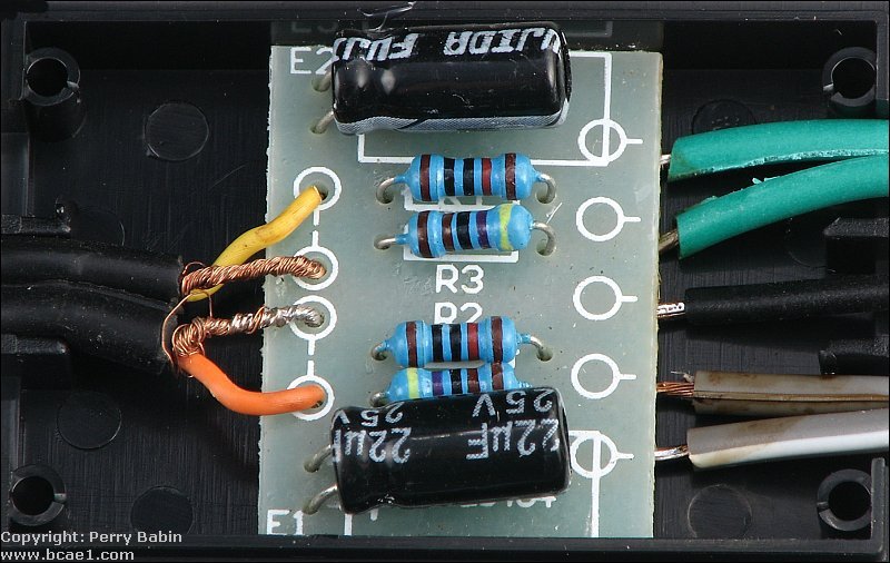
First, let's look at the most basic line output converter. The one below would not be suited to convert the speaker output from any head unit or amplifier that has DC biasing (half of the B+ voltage) on its speaker terminals. This one acts as a voltage divider (covered on the Resistors page) to simply reduce the signal level. These can work on some OEM amplifiers but should probably be avoided for most installs. These have no transformers so they cannot provide any isolation and cannot effectively block the pulse of DC that DC biased amps will have. The high-power line output converter is better suited for those.
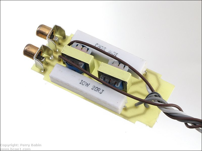
A high powered line output converter consists, primarily, of a transformer and often a high power resistor (commonly a10 watt resistor). The resistor is used to load the amplifier in the head unit. Some amplifiers will exhibit less than ideal manners when they are unloaded. Remember that we said that the head unit's outputs had a large quick increase in DC voltage when the head unit is switched on. The transformer will pass the difference in voltage between the two input terminals. Since the DC voltage increases simultaneously on both of the input terminals of the line output converter (and therefore the transformers in the converter), the pulse of DC is canceled out. If the line output converter simply used resistors as a voltage divider (with no transformer), the turn on pop would be severe for most amplifiers.
Another benefit of using transformers in the converter is that it allows the shield ground on the output of the converter to float. This means that it can be grounded to any point in the vehicle and there will be no chance of creating a ground loop between the output shield ground and the head unit's ground.
----- Critically Important -----
Flash graphics viewing/use alternatives:
Flash support by most modern browsers has been dropped but that's not the end of the line for Flash.
There is no practical alternative to Flash for the interactive demos/applets/graphics on this site.. Especially when there are alternatives, some simple, some good, some...
Ruffle is chosen by most because they can't imagine using anything but their preferred browser. It works. It's OK but not great. The Flash graphics won't look as they're supposed to but it, generally, works.
The #1 preferred (by me) way to view the site and the Flash graphics is with the Chromium Portable browser and the installation of the older (no time-out) Flash Player files. This was incredibly simple when people knew computers but not today when people only know how to work with their phones.
The Flash Browser is a good option but it's so stripped down that it makes it somewhat difficult to use.
The Maxthon browsers are an option. The v4.95 is the easiest (install and use). V5.3.8 and 6.1.0 require (very) slightly more effort (very).
The Chromium and Maxthon browsers on the page above are 'portable' browsers. They are not installed into your system. They are simply made available for use on your computer. They can be carried around on a Flash drive and used on any computer.
----- Critically Important -----
Shield ground wires:
There are usually 1 or 2 extra wires on a line output converter (often brown in color). These wires are used to ground the shield of the RCA output cables to the head unit. Some amplifiers work fine without them, others don't. If the converter is installed behind the radio, I would recommend connecting the shield ground wires to the case of the radio. The next diagram shows a schematic diagram for a simple line output converter.
Note:
The images above/below shows the loading resistors. These are designed to withstand the voltage from a head unit (some are designed to withstand a bit more and are made to be used with small car amps). Many people want to use a line output converter with a home stereo receiver. This is not generally a good idea. Home stereos are designed to produce rated power into higher impedance loads. This means that they typically drive higher voltages into the speakers. The line output converters designed for car audio typically cannot handle the power that home amplifiers/receivers can drive into them. This, at the very least, can destroy the converter. At worst, it could be a fire hazard.
The following image shows what the inside of a basic line output converter looks like.
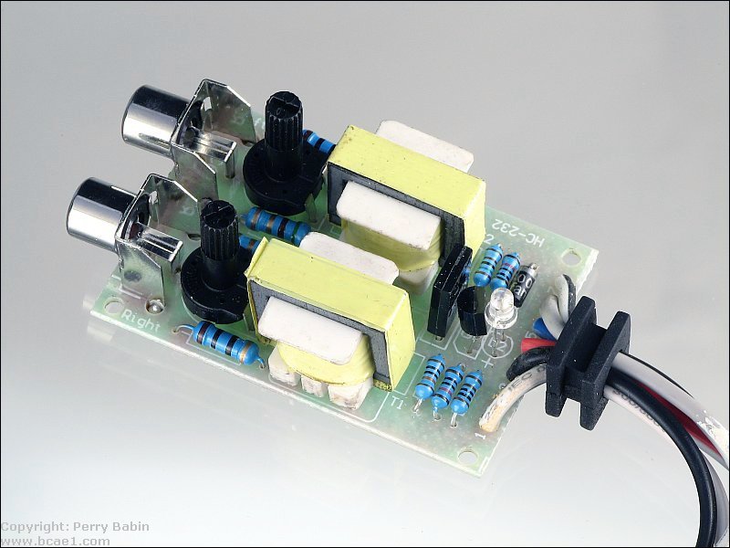
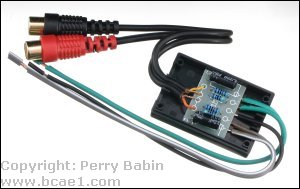
This next line output converter is a bit different than the previous one. This one adds the ability to produce a remote turn-on output. When the converter receives an input with DC bias, it drives 12v to the remote output wire (blue). The B+ and ground wires must be connected for the remote output and the LED power indicator to work. The two potentiometers near the RCA jacks are level controls for the preamp outputs. This converter doesn't have the loading resistors or the shield ground wires that the previous converter had.
This site was started for pages/information that didn't fit well on my other sites. It includes topics from backing up computer files to small engine repair to 3D graphics software to basic information on diabetes.
This site introduces you to macro photography. Macro photography is nothing more than the photography of small objects. It can take quite a while to understand the limitations associated with this type of photography. Without help, people will struggle to get good images. Understanding what's possible and what's not possible makes the task much easier. If you need to photograph relatively small objects (6" in height/width down to a few thousandths of an inch), this site will help.
If you're interested in air rifles, this site will introduce you to the types of rifles available and many of the things you'll need to know to shoot accurately. It also touches on field target competition. There are links to some of the better sites and forums as well as a collection of interactive demos.
This site helps anyone new to computers and anyone with a basic understanding of computers with a desire to learn more about the internal components of a computer. If you have a computer that you'd like to upgrade but don't know where to start, this is a good site for you.
This site is for those who want to begin racing karts but don't fully understand how the various parts work. It's mostly interactive demos that show how the various parts of the kart work.
Click HERE to visit a friend's new car audio tech site.


 Line output converters (LOCs) are used to convert a head unit's speaker outputs or the outputs of an OEM amplifier into a signal suitable to drive the preamp inputs of an amplifier. Most line output converters (LOCs) used in the past few years are designed for high output head units.