Ground loop isolators are used to break the DC circuit path for the audio shield ground circuit.
Background:
The head unit's preout audio section is referenced to ground (the metal outer chassis of the head unit to be more precise). This means that the audio output's reference is tied to the mounting position of the head unit.
You already know that ALL conductors have resistance. This includes the vehicle's metallic chassis. Any time that you have current flowing through a conductor (which, as you remember, has resistance) you will have a voltage drop across the conductor.
Any accessory (lights electric motors etc...) which are grounded to the body will cause varying voltages across the conductor (the body of the vehicle). If you could measure the voltage from the ground for your amplifier to the ground for the head unit, you would see a very small difference of voltage even though they are both ground. To make matters worse, the alternator produces small pulses which aren't completely filtered out by the battery and/or capacitors. These pulses create noise that varies with engine (and therefore alternator) speed.
Note:
This next paragraph will become agonizingly redundant. It is an attempt to make the concept clear to those who are new to car audio.
Ground Loops:
Every piece of car audio equipment has some type of noise canceling circuit on the audio input circuit. These input circuits will, ideally, completely isolate the audio's shield ground from the amplifier's internal connection chassis ground. The amplifier's input shield connection (if properly designed) will have virtually no connection to the amplifier's power ground. It should take the signal from the RCA cable's center conductor, compare the center conductor's signal to the RCA's shield (the reference) and amplify the difference between the two. Remember the voltage generated in the body (voltage drop across the chassis from other electrical accessories)? Well if the amplifier used the ground in the rear of the vehicle (where the amplifier is mounted) as the audio reference instead of the shield ground (which is referenced to ground at the head unit's mounting position) as a reference, the voltage generated through the body would become part of the amplified signal. The amplifier would amplify the difference between the signal on the center conductor of the RCA cable and the amplifier's ground (in the rear of the vehicle). Some manufacturers use poorly designed input circuitry which allows the equipment's power ground to have too much of an influence on the signal (not enough isolation). This causes a small amount of fluctuating DC current to flow through the audio shield which allows noise (from the voltage drop across the chassis) to enter the signal path. The 2 ground paths create a ground loop.
Lame Analogy:
For those of you who are more mechanically inclined, try to think of it as a brake cable for the rear brakes on a bicycle. You know that there's an outer casing and a center cable. If there was no outer casing (only a cable connected to the brake lever). The brakes would work properly only when the handle bars were in precisely the right position (straight ahead for this example). If the handle bars were turned a little to one side (let's say left), the cable would get slack and could not possibly tighten the calipers onto the rear wheel. If the handle bars were turned sufficiently to the right, the cable would tighten and the brakes would be applied no matter whether the brake lever was pulled or not. The brake cable's outer casing acts as a reference for the braking system. If the inner cable at the brake lever end moves 1 inch with reference to the casing, it will do the same thing on the other end (the caliper end of the cable). It does not matter how much the two opposite ends of the cable (as a whole) are moved (with reference to each other). The RCA cable provides a reference along with the signal to make sure that the signal is accurate when it reaches the other end. If you want add a 'ground loop' to the braking system, imagine a stiff rubber band connecting the brake lever to the rear caliper. If you adjusted the brakes to operate properly with the handle bars straight, the braking would not work precisely the same when you turned the bars to either side. The brake cable would dominate the braking operation and the brakes would probably work fairly well, but not perfectly because there would be 2 different forces trying to control the rear caliper. This would form the mechanical version of the ground loop.
----- Critically Important -----
Flash graphics viewing/use alternatives:
Flash support by most modern browsers has been dropped but that's not the end of the line for Flash.
There is no practical alternative to Flash for the interactive demos/applets/graphics on this site.. Especially when there are alternatives, some simple, some good, some...
Ruffle is chosen by most because they can't imagine using anything but their preferred browser. It works. It's OK but not great. The Flash graphics won't look as they're supposed to but it, generally, works.
The #1 preferred (by me) way to view the site and the Flash graphics is with the Chromium Portable browser and the installation of the older (no time-out) Flash Player files. This was incredibly simple when people knew computers but not today when people only know how to work with their phones.
The Flash Browser is a good option but it's so stripped down that it makes it somewhat difficult to use.
The Maxthon browsers are an option. The v4.95 is the easiest (install and use). V5.3.8 and 6.1.0 require (very) slightly more effort (very).
The Chromium and Maxthon browsers on the page above are 'portable' browsers. They are not installed into your system. They are simply made available for use on your computer. They can be carried around on a Flash drive and used on any computer.
----- Critically Important -----
Construction:
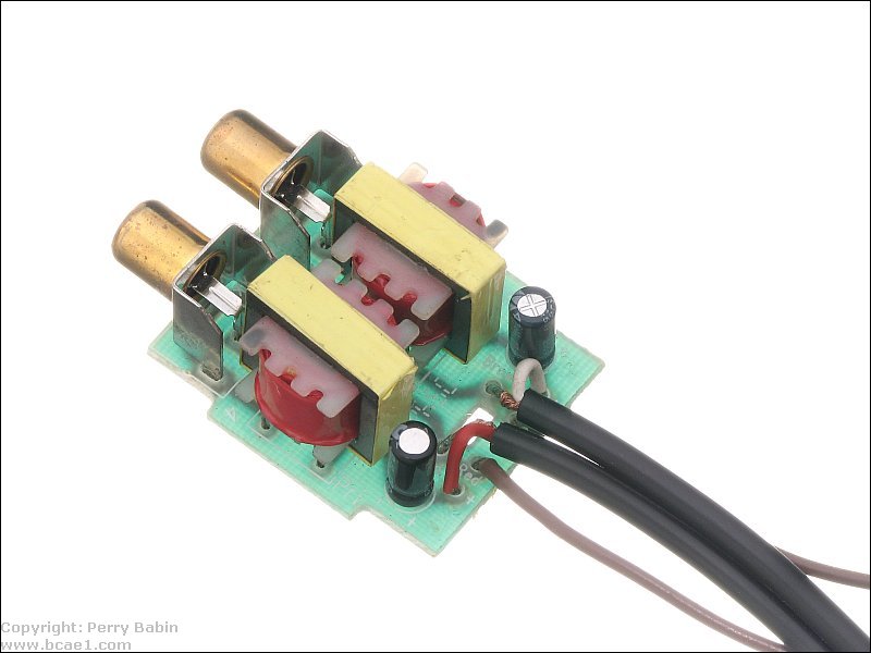
A ground loop isolator uses an isolation transformer for each channel. The transformers generally have a 1:1 ratio which neither boosts nor cuts the audio level. They are typically bi-directional (either end can be and input or an output) but there are some that have and input and an output. When you see the jacks/plugs marked as input/output, connect it as indicated. In the isolation transformer, the audio is magnetically coupled through the transformer's core. Since DC cannot flow the transformer, the DC path is cut and the noise is eliminated (if the noise was caused by a ground loop).
The following is an example of a generic ground loop isolator.
Note:
Many of the ground loop isolators (particularly those sold on eBay) have a current rating on them. Preamp level noise filters (ground loop isolators) essentially have no current passing through them. There is a very tiny bit of current that's required to pass the audio signal but it's less than 0.0005 amps of current in most cases. The old style noise filters that are used in the B+ line must pass current but those are rarely used (and when they are, they're genrally useless). Preamp level ground loop isolators have RCA connectors and rarely have power/ground connections. If you're looking for a ground loop isolator and you see a current rating on them, it's not likely made by a trustworthy company.
This site was started for pages/information that didn't fit well on my other sites. It includes topics from backing up computer files to small engine repair to 3D graphics software to basic information on diabetes.
This site introduces you to macro photography. Macro photography is nothing more than the photography of small objects. It can take quite a while to understand the limitations associated with this type of photography. Without help, people will struggle to get good images. Understanding what's possible and what's not possible makes the task much easier. If you need to photograph relatively small objects (6" in height/width down to a few thousandths of an inch), this site will help.
If you're interested in air rifles, this site will introduce you to the types of rifles available and many of the things you'll need to know to shoot accurately. It also touches on field target competition. There are links to some of the better sites and forums as well as a collection of interactive demos.
This site helps anyone new to computers and anyone with a basic understanding of computers with a desire to learn more about the internal components of a computer. If you have a computer that you'd like to upgrade but don't know where to start, this is a good site for you.
This site is for those who want to begin racing karts but don't fully understand how the various parts work. It's mostly interactive demos that show how the various parts of the kart work.
Click HERE to visit a friend's new car audio tech site.