A DC power supply is used in place of a 12 volt battery when you need to operate car audio equipment and the only source of power is the mains voltage (AC wall outlet). This type of power supply is similar to a battery charger but has much better 'manners'. A battery charger is generally unregulated. Some high current battery chargers will produce up to 17 volts as the battery reaches it fully charged state. The regulated DC power supplies will not go above their regulated voltage. The regulated DC power supply should not be connected to a dead battery. Since it is designed to maintain a constant output voltage, it will instantly try to bring the battery's voltage up to its regulated voltage and may blow its internal fuses or be damaged (depending on its design). A good DC power supply will not cause a hum like a battery charger will (which is important when you want to listen to your system for extended periods of time or when tweaking your system).
Linear DC power supplies:
A linear power supply uses its output transistors in much the same way as class A or class A/B amplifiers use their output transistors. This means that, when the supply is in use, there's current flowing through the transistors and a voltage drop across the transistors. This type of supply has little or no high frequency noise present at its output terminals but the transistors (operating in a linear mode) produce a lot of heat when driving heavy loads. They also tend to have very large, heavy transformers.
Switching DC power supplies:
A switching power supply uses its output transistors much like the switch-mode power supply in your amplifier or like the output transistors of a class D amplifier. This means that the output transistors are either fully on or fully off. There is, in theory, no current flowing through the transistors when there is a voltage drop across the transistors and there is no voltage drop across the transistors when current is flowing through them. These power supplies are very efficient and produce relatively little heat when compared to their linear mode counterparts. They are slightly noisier than linear power supplies (especially high frequency noise). These supplies are smaller and more lightweight than linear power supplies.
Power supply features:
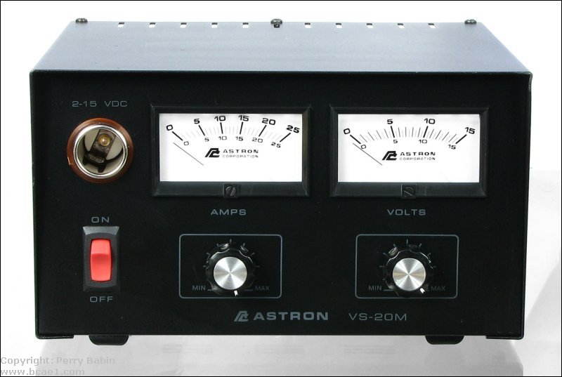
Voltage and current meters:
These meters let you monitor the output voltage and current of the power supply. The current meter is very nice to have when testing equipment. It will quickly let you know if the device under test is pulling too much current.
Voltage and current output controls:
These controls allow you to set the output voltage and limit the output current of the supply.
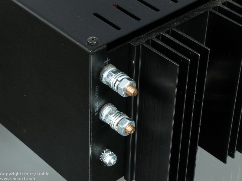
Output Terminals:
The output terminals are where you make your connections to the PS. Heavy duty power supplies typically have studs like the one below. Cheaper supplies or power supplies rated for less current commonly have 'binding posts'. Binding posts give you more options but aren't capable of passing significant current for long periods of time.
For those who want to use a car audio amplifier in their home...
Using all car audio equipment:
This diagram shows how the power and ground connections would be made to the power supply. You notice that there are fuses on all of the wires that are connected to the power supply's positive terminal. These are ABSOLUTELY necessary. It is just as easy to start an electrical fire indoors as it is in a car. 5 amp fuses should be sufficient in the radio's power wires. The amplifier's fuse would be determined by the amplifier's current draw requirements. You should read the Fuses page of this site for more info. The radio and the amplifier would operate precisely as they do in the vehicle in this configuration.
----- Critically Important -----
Adobe has deemed that the Flash content on web pages is too risky to be used by the general internet user. For virtually all modern browsers, support for Flash was eliminated on 1-1-2021. This means that those browsers will not display any of the interactive Flash demos/calculators/graphics on this (or any other) site.
The simplest (not the best) fix, for now, is to download the Ruffle extension for your browser. It will render the Flash files where they were previously blocked. In some browsers, you will have to click on the big 'play' button to make the Flash applets/graphics visible.
An alternative to Ruffle for viewing Flash content is to use an alternative browser like the older, portable version of Chrome (chromium), an older version of Safari for Windows or one of several other browsers. More information on Flash capable browsers can be found HERE. It's not quite as simple as Ruffle but anyone even moderately familiar with the Windows Control Panel and installation of software can use Flash as it was intended.
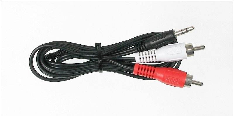
Either of the next two will work with your MP3 player. Instead of connecting the home receiver to the amplifier, you would connect the output of your MP3 player to the amp using a cable to adapt the MP3 player's headphone jack to the amplifier.
Driving a car audio amplifier from a home receiver (example #1):
If you want to use a home receiver with your mobile amplifier and you're lucky enough to have a receiver with a set of preamp output and main amplifier input jacks, you would connect your system as shown in the following diagram. The level of the audio from the preamp output jacks are controlled by the volume control. You may have to connect the power supply's ground to the ground screw on the back of your receiver to prevent/reduce AC hum. If you only want to use your external amplifier for bass and want to continue using the receiver's internal amplifier to driver other speakers, you will have to use Y-cables to split the signal. In the image below, the bars connecting the preamp output and main input jacks are simply what's used to connect the preamp output signal to the receiver's internal amplifier.
Driving a car audio amplifier from a home receiver (example #2):
If your receiver does NOT have pre out/main in jacks, you will have to use the tape monitor output jacks and an external amplifier. This type of setup will NOT work well if you are driving speakers from the receiver's speaker level outputs. You will also have to use an external volume control to control the audio output levels. The audio output from the tape monitor outputs is NOT controlled from the receiver's volume control. You can find the full description of the volume control on the potentiometers page of this site.
Note:
Some people want to use a line output converter to drive car amplifiers with a home receiver. Sometimes the LOC will have a relatively low impedance (4 ohms) loading resistor. This may overload the outputs in some receivers. If you want to use an LOC, insert a 1 or 2 amp fuse in series with the receiver's positive speaker output terminals which are to drive the LOC. Don't try it without the fuses.
Power Supply Current Calculator
Enter the total power output of all of your amplifiers, length of the power wire, wire gauge you intend to use, battery (power supply) voltage and amplifier efficiency below.
It will calculate the current draw at full power output.
Note: Class A/B amplifiers (most amplifiers) are generally 50-60% efficient at full power. Class D amplifiers are about 70-80% efficient at full power. Both are much less efficient at less than full power.
Notice how the current draw increases as the efficiency decreases (and vice versa).
An amplifier will draw less current at low to moderate volume than it will at full power output. You may be able to get by with a power supply smaller than indicated by the calculator.
This calculator was originally designed to calculate voltage drop in power wire. If there's anything you don't understand about the data generated, refer to the wire page.
Note:
If there was a warning of too few circular mils in the calculator above, the wire that you've chosen may have problems with overheating at full power. You will get this warning when you punch in the numbers for something like a short piece of 8g wire to go between the distribution block and the amplifier. Some people use a single strand of 8g wire to make the connection between the dblock and an 800 or 1000 watt amp. Even though the voltage drop in that short piece of wire may not be significant, the power dissipation may be significant. The value of 300 circular mils per amp of current is somewhat arbitrary and may lead to some arguments but it is a safe value. I originally used the power dissipation per foot as the reference for the warning but it didn't hold for all wire sizes. Larger wires have more surface area and can dissipate more power per foot.
This site was started for pages/information that didn't fit well on my other sites. It includes topics from backing up computer files to small engine repair to 3D graphics software to basic information on diabetes.
This site introduces you to macro photography. Macro photography is nothing more than the photography of small objects. It can take quite a while to understand the limitations associated with this type of photography. Without help, people will struggle to get good images. Understanding what's possible and what's not possible makes the task much easier. If you need to photograph relatively small objects (6" in height/width down to a few thousandths of an inch), this site will help.
If you're interested in air rifles, this site will introduce you to the types of rifles available and many of the things you'll need to know to shoot accurately. It also touches on field target competition. There are links to some of the better sites and forums as well as a collection of interactive demos.
This site helps anyone new to computers and anyone with a basic understanding of computers with a desire to learn more about the internal components of a computer. If you have a computer that you'd like to upgrade but don't know where to start, this is a good site for you.
This site is for those who want to begin racing karts but don't fully understand how the various parts work. It's mostly interactive demos that show how the various parts of the kart work.
Click HERE to visit a friend's new car audio tech site.


 A DC power supply is used in place of a 12 volt battery when you need to operate car audio equipment and the only source of power is the mains voltage (AC wall outlet). This type of power supply is similar to a battery charger but has much better 'manners'. A battery charger is generally unregulated. Some high current battery chargers will produce up to 17 volts as the battery reaches it fully charged state. The regulated DC power supplies will not go above their regulated voltage. The regulated DC power supply should not be connected to a dead battery. Since it is designed to maintain a constant output voltage, it will instantly try to bring the battery's voltage up to its regulated voltage and may blow its internal fuses or be damaged (depending on its design). A good DC power supply will not cause a hum like a battery charger will (which is important when you want to listen to your system for extended periods of time or when tweaking your system).