
|
| Email Home Page |
|
|
|
|
| Email Home Page |
|
|
|
----- Critically Important -----
Adobe has deemed that the Flash content on web pages is too risky to be used by the general internet user. For virtually all modern browsers, support for Flash was eliminated on 1-1-2021. This means that those browsers will not display any of the interactive Flash demos/calculators/graphics on this (or any other) site.
The simplest (not the best) fix, for now, is to download the Ruffle extension for your browser. It will render the Flash files where they were previously blocked. In some browsers, you will have to click on the big 'play' button to make the Flash applets/graphics visible. An alternative to Ruffle for viewing Flash content is to use an alternative browser like the older, portable version of Chrome (chromium), an older version of Safari for Windows or one of several other browsers. More information on Flash capable browsers can be found HERE. It's not quite as simple as Ruffle but anyone even moderately familiar with the Windows Control Panel and installation of software can use Flash as it was intended.
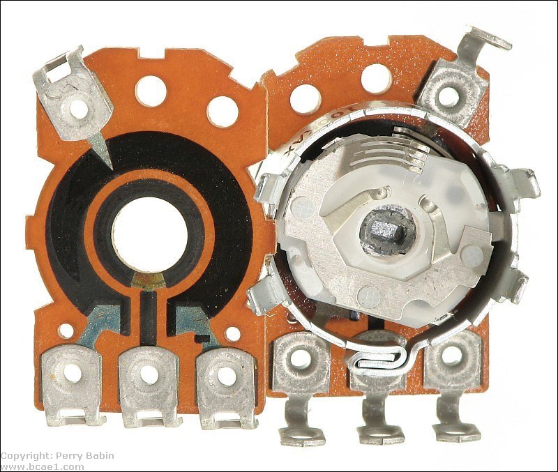
The following diagram shows how the schematic symbol relates to the drawing of the potentiometer.  This is the inside of the potentiometer shown at the top of the page. The back has been removed and placed next to rest of the potentiometer. The left side shows what the resistive element looks like. It's the wider black area. The inner ring with the line that goes to the center terminal is a non-resistive conductor that passes the signal/voltage from the wiper to the center terminal.
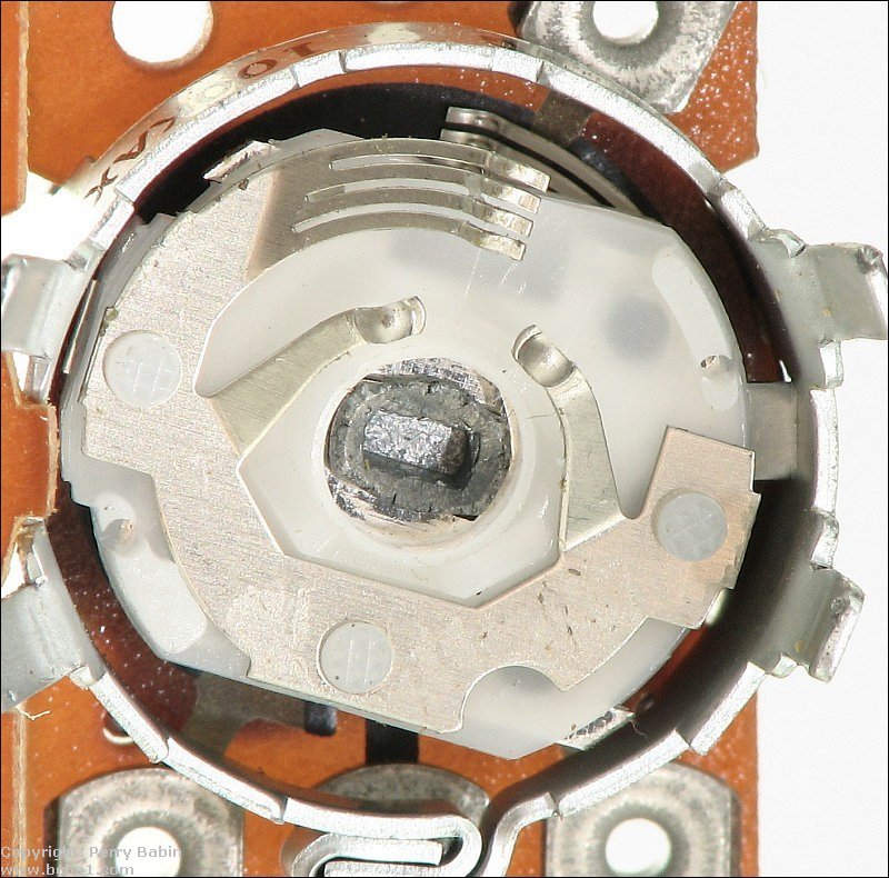
 Below is a close-up photo of the wiper mechanism. The four parallel contacts at the top make contact with the resistive element. The two contacts below those make contact with the inner ring. If you look 'behind' the white insulator, you can see the wiper contacts for the other half of the potentiometer touching the resistive element.
A Potentiometer as a Variable Voltage Divider:
�
This means that the resistance of the resistive element increases in direct proportion to the distance traveled along the resistive element. In the middle of travel, the resistance from the sliding terminal to either of the other terminals is half of the total resistance.
�The output is simply the voltage at the point where the wiper contacts the resistive element.
Resistance Taper:
In the next diagram, you can see that the slider has been moved toward the positive terminal. This means that the output voltage will be higher than 6 volts. In this case the output voltage is 7.5 volts DC. If the slider was moved closer to the negative terminal, the voltage would be lower.
Output with AC:
Rotary Potentiometers:
Power Ratings:
In the picture below, at the top is a multi-section potentiometer used in older head units. Below, various styles of printed circuit board potentiometers. 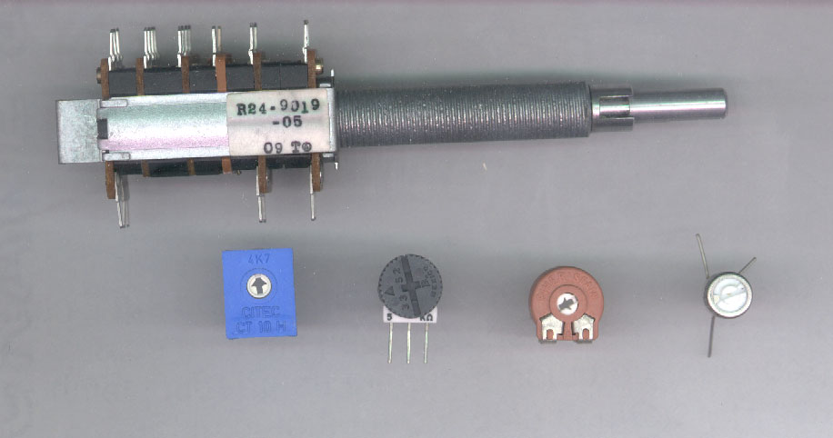
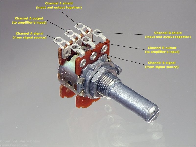
The images below show how to wire a volume control to be inserted into the preamp line. If noise is a problem when you touch the metal shaft, ground the metal part of the potentiometer. A ring terminal around the threaded bushing is probably the best way to ground it. A potentiometer specifically designed for use as a volume control (a pot with a 'logarithmic' taper) will give the most linear volume control. The Radio Shack part # 271-1732 is a good choice. To connect between two components (head units and amplifiers or head units and crossovers), you would use RCA connectors for the input and output. For those using an MP3 player (iPod, iPad, cell phone...), you would use whatever connector is needed on the input to fit the MP3 player.
 Below, you can see one half of the potentiometer connected to the shielded cable. It doesn't matter which half of the pot you use for left and right. The two halves are identical. In this photo, you can see which shielded cable each of the red wires comes out of. The top black cable would go to the amplifiers or crossover. The bottom black cable would go to the signal source (head unit or MP3 player). You can see how the shields for both cable (input and output for the channel) are tied together.
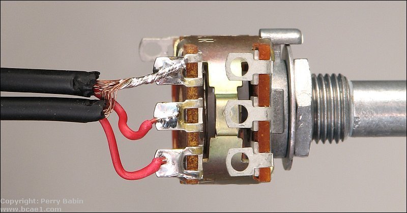 Above, notice how the shields are tightly twisted together except for a short length near where they enter the insulated part of the cable. This is done for a reason. If you tightly twist the shield all of the way to the insulator, the heat will be efficiently transferred through the braided shield to the insulation for the center conductor. This can cause strands of the shield to melt into the insulation which will allow either constant or intermittent contact with the center conductor. When the shield contacts the center conductor, the signal will be shorted to ground and no audio will pass to the next component.
|
|
You should remember: 1.The voltage on the wiper terminal of a linear taper potentiometer has a voltage which is directly proportional to its physical position along its resistive element. |

|

|
|

|
 There are many instances where only a portion of an output voltage from a signal source is needed. If we allowed the full output voltage from a home CD player to be driven into the input of an amplifier, the amplifier would play at or near full power at all times. This would become quite annoying in a very short period of time. To reduce the overall volume, we need to allow only a fraction of the full signal through to the amplifier. To control the level of the signal, we use a potentiometer. A potentiometer (also know as a 'pot') is a resistor with a movable tap. Potentiometers can be used to allow a change in the resistance in a circuit or as a variable voltage divider (in the case of a volume control). If you have a rotary volume control that doesn't click when rotated, it is (more than likely) a potentiometer being used as a variable voltage divider. If your volume control clicks and steps the volume up or down with each click, it's probably a rotary encoder (a switch), not a potentiometer. A potentiometer generally has 3 terminals. 2 of the terminals are connected (internally) to the opposite ends of a resistive element. The 3rd terminal is called the wiper. It is generally located in-between the other 2 terminals. The wiper is a contact (actually, generally several very small contacts) that makes contact along the resistive element. The diagram below shows the schematic symbol for a potentiometer.