
|
| Email Home Page |
|
|
|
|
| Email Home Page |
|
|
|
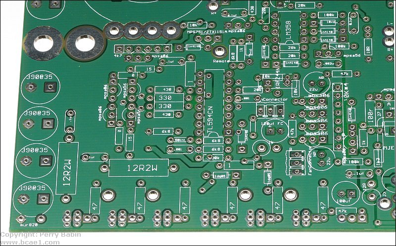
A printed circuit board is a fiberglass board (better quality boards, anyway) which is typically 1/16" thick. It is plated with copper on 1 or more sides (sometimes multi-layer boards are used). To print the circuits onto the board, the copper plating is coated with a protective material on all areas where the copper is to remain on the fiberglass substrate. The board is then 'bathed' in a corrosive solution which dissolves all of the UNprotected copper areas. This leaves only the copper traces needed to complete the connections between the electronic components of the device.
In the circuit board below, the lighter colored areas show you where the copper was protected. The copper areas are used instead of wires. If components had to be connected with wire, the reliability would be poor and the equipment would be much more expensive due to the labor involved in its assembly. The dark green ares are the bare fiberglass where the copper has been removed. There are no components mounted in this board yet. The shiny 'pads' are where the component's leads will be soldered into place. You can see the hole in the center of the pad where the component's electrical leads will pass through the board. The green coating is a 'solder mask' which prevents solder from bridging between traces and pads and also prevents the copper from oxidizing.
Markings: Prefix:
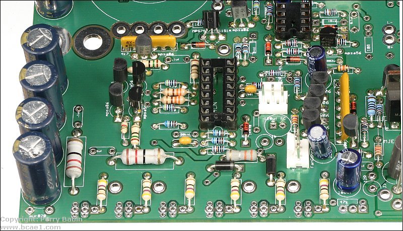
This is the same board after being populated (having parts installed).
 |

|

|
|

|