| Email Home Page |
|
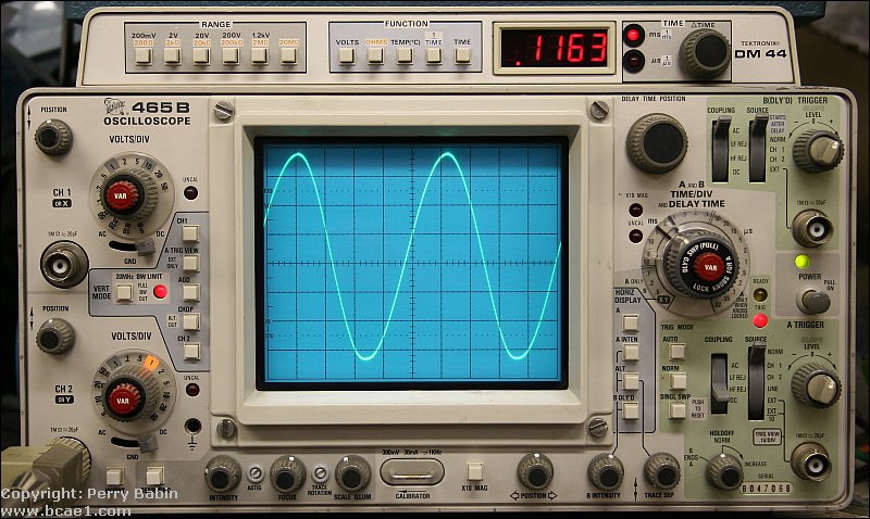
The most common oscilloscopes use a cathode ray tube (CRT) similar to the picture tube in a television. The CRT 'shoots' an electron beam at a charged, phosphorous coated screen. When the electrons hit the screen they excite the phosphorous atoms and cause them to give off light. The beam is constantly scanning across the screen. When there is no input signal, the beam just scans in a horizontal line. Some of the newer scopes use LCD displays but, in my opinion, the resolution isn't as good as the older, CRT based scopes. When I'm looking at a sine wave, I want to see a smooth line. Not a bunch of jaggies. Until they get the resolution up to that of a high definition computer monitor, I'll stick with the older CRT based scopes.
USB Scopes:
Sound Card Scopes:
There are a number of switches on a scope which have to be set correctly for the information on the display to be of any use.
Inputs:
Focus:
Vertical and horizontal position controls:
Timebase:
Cal/Var:
Trace intensity:
Volts/division:
Trigger source:
Trigger level:
Trigger mode:
AC/DC input coupling:
Vector input:
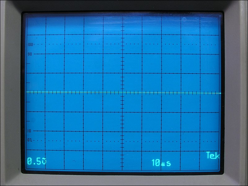
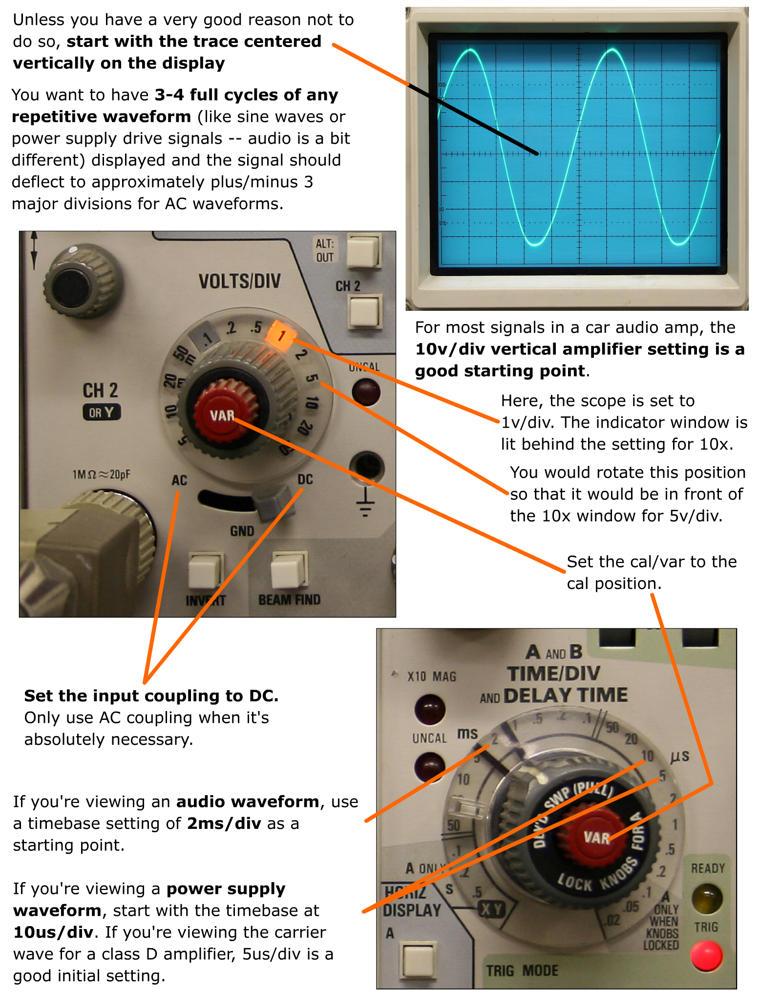
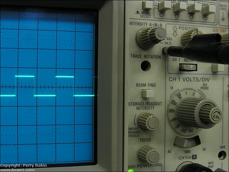
Best Initial Settings: If you're viewing an audio waveform, use a timebase setting of 2ms/div as a starting point. If you're viewing a power supply waveform, start with the timebase at 10us/div. For most signals in a car audio amp, the 10v/div vertical amplifier setting is a good starting point. These are good initial settings but you may need to make slight adjustments (generally only one click up or down) to get the waveform displayed properly. In general, you want to have 3-4 full cycles of any repetitive waveform (like sine waves or power supply drive signals -- audio is a bit different) displayed and the signal should deflect to plus/minus 3 major divisions. In some instances (when a relatively small signal is riding on a significant DC voltage), you may need to switch to AC coupling but this isn't generally necessary. For DC signals that only swing positive (like the gate signals for power supply FETs, in most amps), set it the same but leave it DC coupled and leave the trace centered on the display. It's OK if it doesn't deflect to below the reference line. Some people insist on using AC coupling because they're too lazy to switch to the proper type of coupling. If, for example, you're looking at the drive waveform for the power supply FETs in an amplifier, the coupling and reference is very important. In the next photo, you can see that the trace is aligned to the reference line on the scope's display. This is how it should be aligned every time you use the scope unless you have a reason to move it from the reference. You can see, however, that the scope is set to AC coupling (wavy line over the 'v' in the lower-left corner) and to 0.5v/div. These are wrong for this application. You will see that they've been changed in the next three photos.
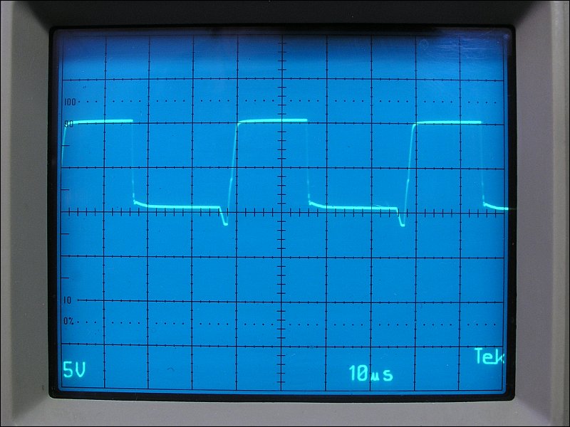
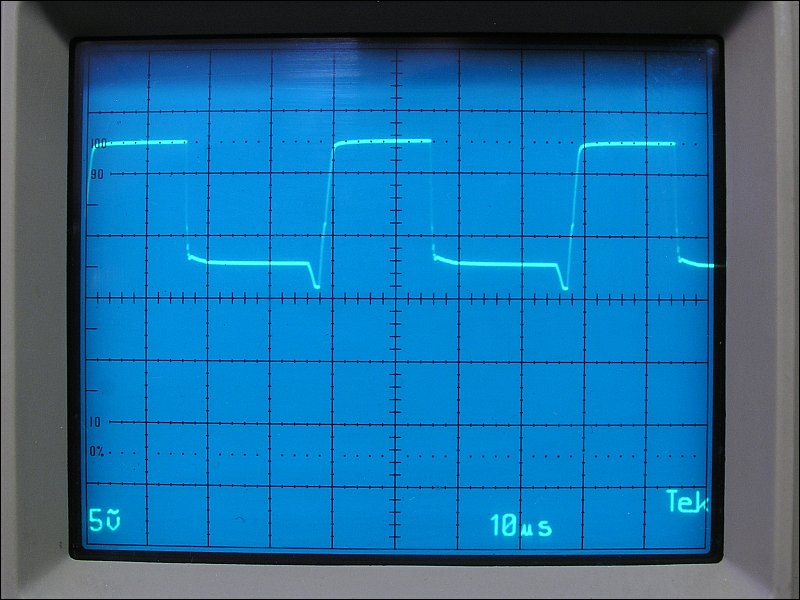
 This photo shows the waveform properly displayed. It's important that the drive voltage drops to below the threshold voltage (turn-on/off voltage) for the FET. For most FETs, that's about 3v DC. It's VERY important to know the voltage with reference to ground. That's why you have to align the trace with the reference line (which represents ground). As you can see, the falling edge of the waveform drops down to about 1.2v above ground before it begins to taper off. This is a good drive waveform.
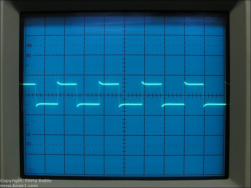
 Below, you can see that the waveform straddles the reference line. The coupling is improperly set to AC instead of DC. Here, you cannot possibly know how close the drive voltage is going (with reference to ground). This is essentially useless as a troubleshooting tool. The waveform could be riding on 3v or more of DC. If you assumed that the waveform was OK but it was riding on 3v of DC (that you can't see due to the AC coupling), and you powered up the amp without using the various safety precautions, the FETs would immediately fail.
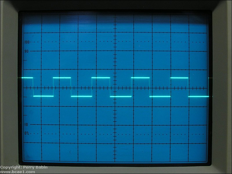
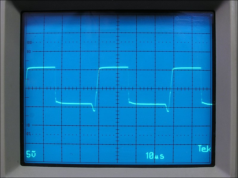 The next waveform is just as useless as the previous one. The trace was not aligned to the reference line. Again, it shows nothing except that there is oscillation.
 If you're asking for help on the forum or via email and you state that you've read this page, I will expect you to know and use all of the settings mentioned above (best initial settings section). Can you answer these questions? You should be able to do so without looking at the previous paragraph.
Save and print the following image and keep it near your scope to check the settings until you get familiar with its settings.
Scope Display Markings:
----- Critically Important -----
Adobe has deemed that the Flash content on web pages is too risky to be used by the general internet user. For virtually all modern browsers, support for Flash was eliminated on 1-1-2021. This means that those browsers will not display any of the interactive Flash demos/calculators/graphics on this (or any other) site.
The simplest (not the best) fix, for now, is to download the Ruffle extension for your browser. It will render the Flash files where they were previously blocked. In some browsers, you will have to click on the big 'play' button to make the Flash applets/graphics visible. An alternative to Ruffle for viewing Flash content is to use an alternative browser like the older, portable version of Chrome (chromium), an older version of Safari for Windows or one of several other browsers. More information on Flash capable browsers can be found HERE. It's not quite as simple as Ruffle but anyone even moderately familiar with the Windows Control Panel and installation of software can use Flash as it was intended.
Click HERE to open this in a new window if you can't see the fine details clearly.
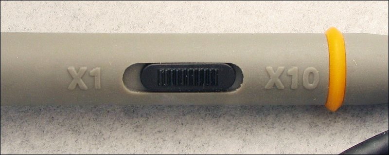
Voltage Measurement: When the scope is set so that the reference line and the trace are aligned (when there is no input to the scope) and you touch the probe to a ground connection in the amp, the trace will not (should not) deflect up or down. If it does, there is a problem with the ground connection between the amp and the scope. The following image initially shows the trace aligned with the reference line. This is VERY important... Too many people have the wrong probe for their scope or don't pay attention to the position of the switch on the probe (for switchable 1x/10x probes). Many times, this means that the scope markings for the vertical amp will be off by a factor of 10. As was stated before, a vertical amp setting of 10v is a good initial setting. To confirm that the scope is working properly, set the vertical amp to 10v and touch the probe to the positive terminal of the 12v power supply. The trace should deflect 1.2-1.5 major divisions. If it does not, you MUST determine why it's not deflecting properly (moving to the proper/expected position on the display). In the following demo, the scope has an input voltage of 12.5v (the voltage on the positive terminal of the imaginary DC power supply). You can see that the scope is set to AC voltage. In the AC coupling mode, it cannot 'see' the DC on the input so the trace does not deflect. If you had the scope set like this (and were not aware of it), you may be checking to see if there was DC on a point and may (erroneously) believe that there was no DC. This can lead to errors and can even be dangerous. Now, click the DC coupling button and see how far the trace deflects. With the scope set to 10v/div, it deflects 1.25 divisions. If you set the vertical amp to 5v, you can see that it deflects 2.5 divisions. If you set it lower than 5v, it will deflect off of the top of the display. At 2v/div, the scope would have to have 6+ vertical divisions (to remain on the display) and it only has 4.
Time Measurement:
The following demo shows how changes in the time base and voltage selector will change the way the waveform is displayed. The signal is a 1kHz 1vpeak (2vp-p) sine wave. Depending on the speed of your processor, there may be a second or more delay between the time you push a button and the time the display is updated. Click HERE to make it fill this window.
This scope has a few added features. The signal is the same 1vpeak (2vp-p) 1kHz signal except for the fact that it has 6 volts of DC offset. This is the type of signal that you'd find on the speaker output wires of a typical high power head unit. Since the volts/division includes DC, selecting a voltage lower than 2 volts (while DC coupling is selected) will result in the sine wave disappearing past the top of the screen. Click HERE to make it fill this window.
Calibrating the Scope Probe:
 For this scope, you simply insert the tip of the probe into the port on the front of the scope labeled 'probe adj'. While it's in the port, adjust the trimmer capacitor on the probe. This is best done with an insulated screwdriver. If you use an uninsulated screwdriver, you may have to make slight adjustments then remove the screwdriver to see if the waveform is square. Other scopes have various types of connectors for the calibration signal. The scope at the top if the page has a loop. The loop also allows you to check the function of a current probe (not very common). You'll also see BNC connectors and small rings. The calibration signal port isn't always labeled as such. Some labels you'll see are cal, calibrate, probe cal, probe adjust, 1kc cal...
 The calibration test signal can also be used to test the function of a scope if a probe isn't included. Simply use a piece of 20g solid wire to connect the calibration signal to the center conductor of the input of the scope. That will allow you to test the scope to see if it's triggering properly and to see if it has a clean trace. If you're going to buy a scope online and the owner says that they cannot test it because they don't have a probe, tell them to test it as described above. If they will not do it, don't buy it unless they expressly offer a warranty. |

|
|

|