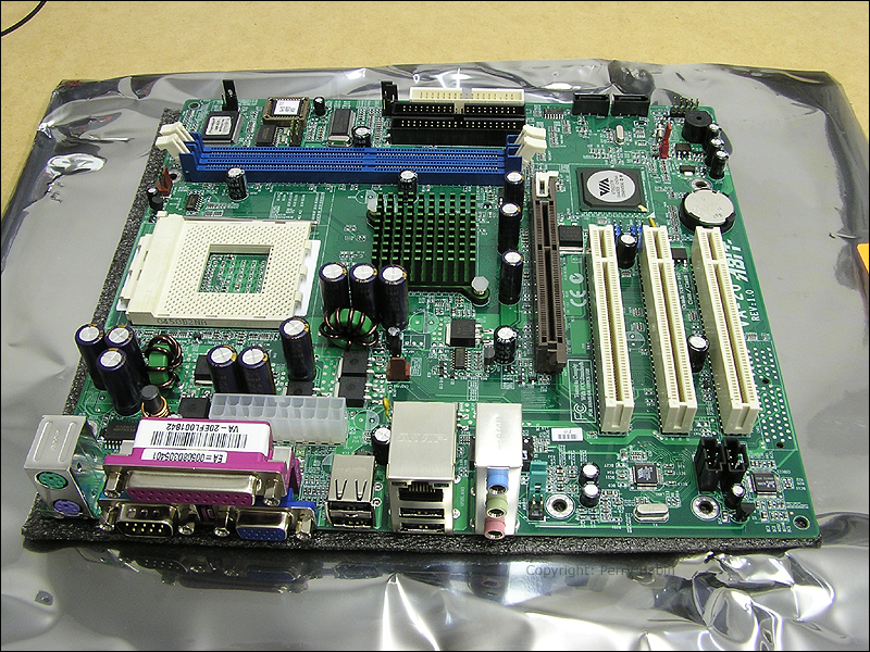
In this first image we can see the rear connectors. This is what you see when you look at the back of your computer. These were covered on the 'The Computer' page of this site. This motherboard was pretty typical in 2005. Newer motherboards are a bit different and use different connectors but this example is still useful.
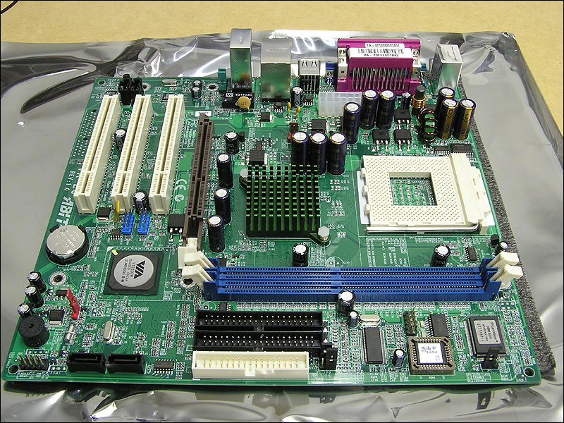
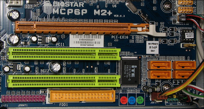
The three white connectors are PCI slots. They can be used with a variety of different devices such as video cards, sound cards video capture cards or LAN cards. PCI and PCI-E slots are significantly different and are in no way compatible. PCI-E slots can be used for an even wider range of expansion cards due to the ability to transfer data at a higher rate. The brown slot is an AGP slot. It's dedicated to video cards. The white lever on the rear of the brown slot is a latch. It assures that the video card stays properly seated. Some newer boards have a lever to lock cards in the PCI-E slots but not all do. Motherboards no longer have AGP slots. They have been replaced with PCI-E (PCI Express) slots. If you're looking at a board that has a long slot with a lever and you don't know if an AGP slot or a PCI-E slot, look on the motherboard near the slot. If it's a PCI-E slot, it's likely labeled as such.
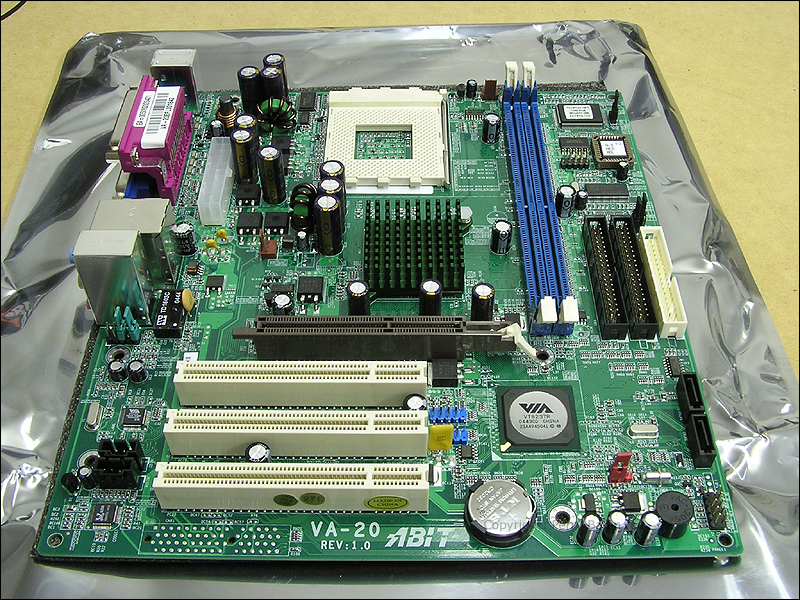
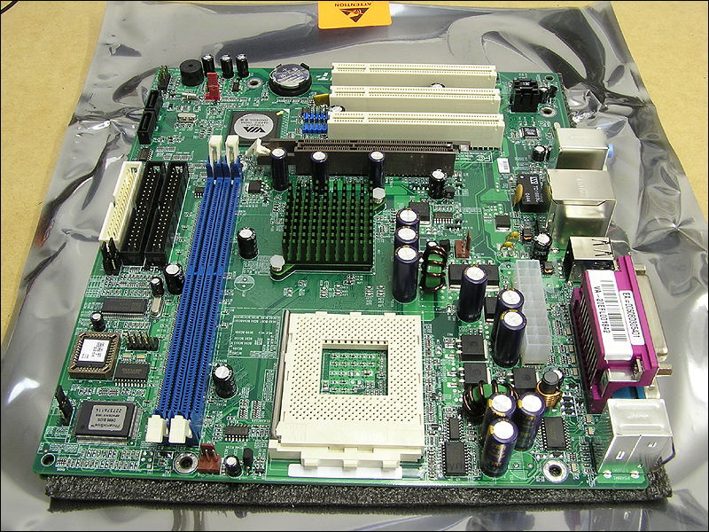
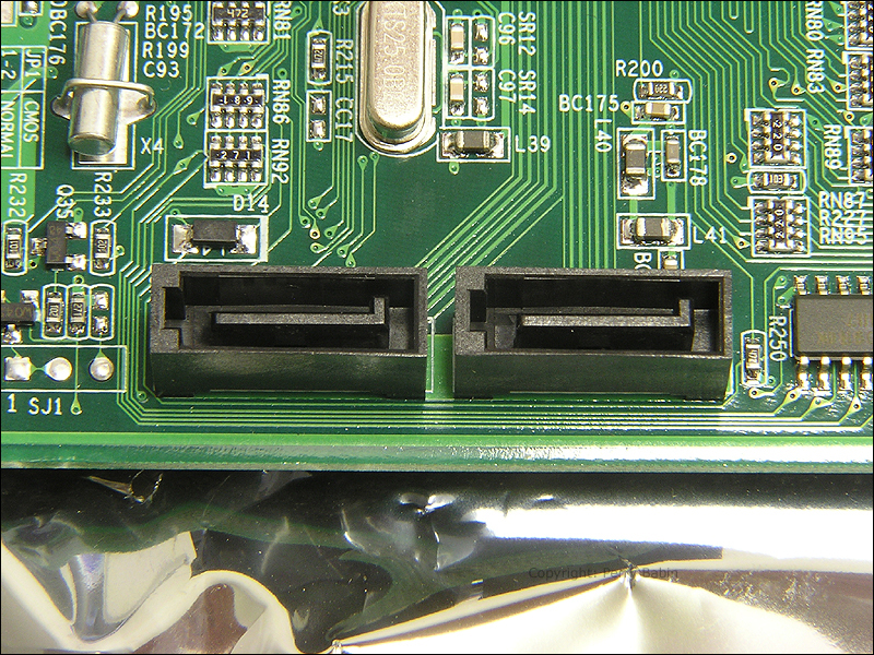
Below, you can see the two black 40-pin IDE connectors as well as the 34 pin floppy drive connector. Many of the newer motherboards have only one IDE connector and no floppy drive connector. Off to the left, you can see the 2 smaller S-ATA connectors. These are used to connect your hard drives and/or optical drives to the motherboard. Newer motherboards can have as many as 8 of these connectors. They are the reason the newer motherboards have only one 40-pin IDE connector. The SATA interface has replaced the IDE interface as the preferred hard drive interface. The two long blue connectors are the memory slots. The arms on the memory slots serve as latches to lock the memory in place. They also help to eject the memory when it needs to be removed. If you are installing the memory and can't close the latches, it means that the memory isn't properly seated.
Here we can see the CPU socket. Just to the right of the CPU socket, you can see the switching regulator. There were pictures of another such regulator in a previous image. This one has larger FETs and heavier wire on the inductors suggesting that it's probably a little better built than the other MB (although the other motherboard is not likely to fail under normal operating conditions).
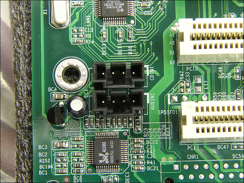
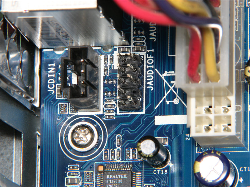
The next image shows the 2 analog audio input connectors. These are typically used for CD ROM drives. Since the CD ROM drive can deliver audio via the 40-pin IDE connection, the analog audio connectors are not generally needed. If you have a video capture card (a card that can accept a video signal from a camcorder or other such device), you may need to use the analog audio input to get the sound into the computer. Other motherboards have a 10 pin connector for audio. OK, it actually has only 9 pins. The missing pin is used as a key to prevent you from connecting similar headers (like USB) to it. When there are no front-panel audio connectors, there will be two jumpers/shunts on the header. When front-panel audio jacks are used, the cable from those connectors plugs onto the 10-pin connector.
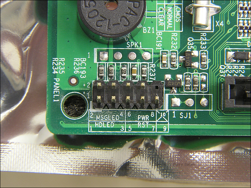
The connector below is where you connect all of the front panel switches and LEDs. There are typically 4 connections (hard drive LED, power/message LED, power switch and reset switch). The LED connections are polarity sensitive (if connected in reverse, the LEDs will not work). The colored wire is generally positive and the white/black wire is negative.
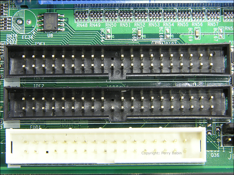
This is a close-up of the IDE connectors. You can just barely see the markings (IDE1, IDE2 and FDD1) over the top edge of the connectors. IDE1 is the 'primary' interface and IDE2 is the 'secondary' interface.
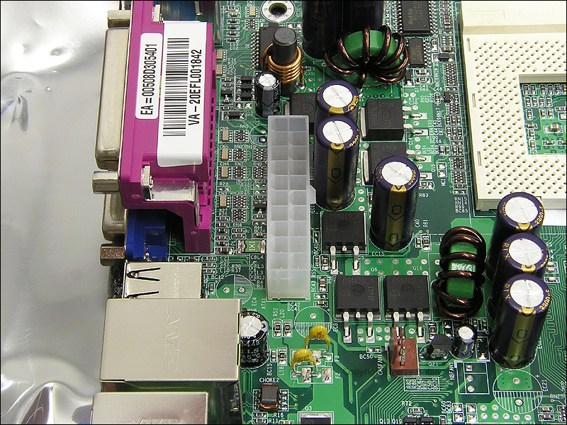
This is a little better picture of the 20-pin main power connector. Newer motherboards use 24 pin connectors. This connector (like most) is keyed so that it can only be plugged in one way. This connector delivers �5vdc, �12vdc and 3.3vdc to the motherboards. Below the power plug, you can see a 3-pin connector. This is for the case fan. Some motherboards can control the speed of various fans. If you're using a small, low current-draw fan, using this connector is OK. If you have large fans that draw lots of current, I recommend plugging the fans directly into a power supply molex connector.
This is a closer view of the S-ATA connectors. You can see that they are also keyed to ensure that the connectors are properly installed.
Chipsets:
Many people believe that the motherboard manufacturer is the determining factor on the features they offer on any motherboard. While this is somewhat correct, the main determining factor is the 'chipset'. The manufacturer chooses the chipset but the chipset determines the features. The chipset determines:
Processor support (AMD/Intel)
Memory support (maximum amount of memory and the memory speed)
Whether the MB has the capability of on-board graphics or not
Support for different types of AGP video cards
Maximum number of USB ports
Maximum number of PCI slots
General audio features (2 channel, 6 channel, 8 channel...)
SATA support
RAID support
Many other features
Northbridge/Southbridge:
The Northbridge is part of the chipset. For the most part, the northbridge is the interface between the processor and most of the rest of the motherboard components. The Front Side Bus is the pathway between the processor and the northbridge. Except for the high end systems, the memory, AGP cards, and the southbridge are connected to the northbridge. On newer, faster systems, the memory is directly connected to the processor. Almost everything else (PCI bus, audio, ethernet, disk controllers, the keyboard and mouse) is either directly or indirectly connected to the southbridge chip.
Motherboard Specifications
While I don't like to get too specific on something that changes as fast as computers, I will do so here to help make things clear. The following is a list of specifications of the motherboard I used above. After each of the specifications, I will give a short description of what they mean.
Supported CPU: Socket A AMD AthlonXP/Athlon/Duron/Sempron Processors
This tells you what CPUs are compatible with the socket on the motherboard. Generally, there is only one CPU socket but there are some newer boards that have 2 sockets to allow upgrading to a CPU that requires a different socket. There are also 'server' boards that have dual processors to allow higher performance.
Chipset: VIA KM400A + VT8237
This tells you what chipset it uses. Here the chipset consists of the VIA KM400A northbridge IC and the VIA VT8237 southbridge IC.
FSB: 200/266/333/400MHz
This is the different Front Side Bus speeds that can be used with this board. This board can essentially handle any of the possible bus speeds of any of the compatible processors. Sometimes, you will see a motherboard that can handle only some of the possible FSB speeds like 200, 266 and 333. In that instance, a CPU that had the ability to run the FSB at 400MHz would not be able to operate at its highest speed. For maximum performance, you need a motherboard that can support the maximum FSB of the CPU you're using.
RAM: 2x DIMM support DDR 400/333/266 Max 2GB
Here, you find the number of sticks of RAM you can use and the maximum amount of RAM that you can use. For example, if you want to use 1G of ram with this board, you could use either 2x512MB sticks or 1x1GB stick.
Slots: 1x AGP 4X/8X, 3x PCI
This tells you the number of PCI slots (the white slots) and that it has an AGP slot (not all boards have AGP video graphic card slots). It also tells you that it supports 4x and 8x video cards. This is important for people who need to have high end video cards for gaming.
Ports: 2x PS/2, 1x COM, 1x LPT, 1x VGA, 8x USB2.0(Rear 4), 1x RJ45, Audio Ports
These are the rear panel ports/jacks. The PS/2 ports are for the mouse and keyboard. The com port is a serial data port. The LPT port is the parallel printer port (for older printers without USB capability). The VGA port is the connection for the on-board graphics processor. The USB ports information tells you that the board has the capability to have 8 USB ports and there are 4 on the rear panel. The RJ45 jack is the ethernet connection. The audio ports are where you connect your microphone (if you have one) and the computer speakers. There is also a 'line' input port so that you can get audio INTO the computer if necessary.
IDE: 2x ATA 133 up to 4 Devices
This is for CD/DVD ROM and IDE hard drives. You can connect a maximum of 4 devices to these two ports. They can be in any combination of optical or hard drives.
SATA: 2x SATA with RAID 0/1
These are the connections for the S-ATA drives. This tells you that there are 2 ports (one port per drive) and that it supports RAID-0 and RAID-1 configurations. RAID-0 uses 2 drives as one. In some situations, it can almost double the speed of a single drive. The downside is that you have double the chance of losing everything on both drives (if one fails, you lose everything). In RAID-1, all information is written to both drives. The advantage is security against lost data if a drive fails. The downside is that you don't gain any more storage over a single drive (cost of drive space is effectively doubled).
Onboard Audio: Realtek ALC655 6-Channel AC 97 Audio
This is the audio driver I.C. It determines capability of the input and output system. On this board, you have the capability of 5.1 channels of output but with only 3 audio jacks, some jacks have to pull double-duty. To use the 5.1 channel setup (2 front speakers, 2 surround speakers, a center-channel speaker and a subwoofer), you have to set the system control to the 5.1 setting. In this configuration, you can not use the microphone or line input (which isn't generally a big problem).
Onboard Video: S3 Graphics UniChrome 2D/3D Graphics
This tells you that it has an on-board graphics adapter and that the adapter can interprete both 2D and 3D commands. This is important for games that use 3D graphics. Keep in mind that the on-board graphics will have limited ability. It will be absolutely fine for office applications and watching videos but for high-end gaming, it won't perform well.
Onboard LAN: VIA VT6103L 10/100Mbps PHY
This tells you that the LAN is capable of operating in both 10MHz and 100MHz systems. Older systems were only capable of 10MHz. The newest systems are capable of 1000MHz. The 1000MHz systems are know as Gigabit LANs.
Form Factor: MicroATX
This is the physical size of the board. Most boards are either 'micro ATX' or simply 'ATX'. There are other board sizes but those are by far the most common. Micro ATX boards are smaller than ATX boards and usually have fewer PCI expansion slots.
This site was started for pages/information that didn't fit well on my other sites. It includes topics from backing up computer files to small engine repair to 3D graphics software to basic information on diabetes.
This site introduces you to macro photography. Macro photography is nothing more than the photography of small objects. It can take quite a while to understand the limitations associated with this type of photography. Without help, people will struggle to get good images. Understanding what's possible and what's not possible makes the task much easier. If you need to photograph relatively small objects (6" in height/width down to a few thousandths of an inch), this site will help.
If you're interested in air rifles, this site will introduce you to the types of rifles available and many of the things you'll need to know to shoot accurately. It also touches on field target competition. There are links to some of the better sites and forums as well as a collection of interactive demos.
This site is for those who want to install or update their car stereo. It begins with the most basic electronics theory, progresses into basic transistor theory as well as covering virtually everything associated with car audio.