|
The "Computer":
 The part of the computer that most people refer to as 'the computer' is simply an enclosure or case that holds most of the components that make up a personal computer (a 'PC'). This page will explain the function of some of the components/connectors that are visible from the outside of the computer case. Internal components will be covered later in the tutorial. Some people refer to the computer case as the 'hard drive'. The hard drive is a small part of the computer that's inside the computer's case. This computer has only one optical drive (a drive that uses a laser to read the data from the media -- CD, DVD and Blu-ray drives) and no floppy drive. It's extremely rare for a floppy drive to be included with a new computer. Generally a card reader is installed in the slot where the floppy drive would have been installed.
A quick note...
You may be tempted to move your computer (to get a better look at the back, when moving it from one location to another...). When doing so, you may find a slot under the front of the computer that makes a good hand-hold for the front of the computer. Do NOT use that as a hand-hold unless you know for a fact that the front of the computer is held on by substantial clips or screws. The front panel of many of the after-market cases are held on by pins that take very little effort to pull free. This means that the front panel is not held securely enough to bear weight. If you use this as a handle, the front cover may pull off. If it does, expect the connectors to be ripped off of both ends of the front panel wires. Expect the motherboard connectors to be damaged. Expect the case to be bent and the motherboard to be damaged as the case crashes into the floor. If you want to move your computer, do so but do so carefully.
Front Panel Buttons/Switches:
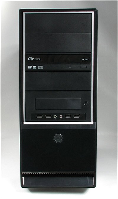
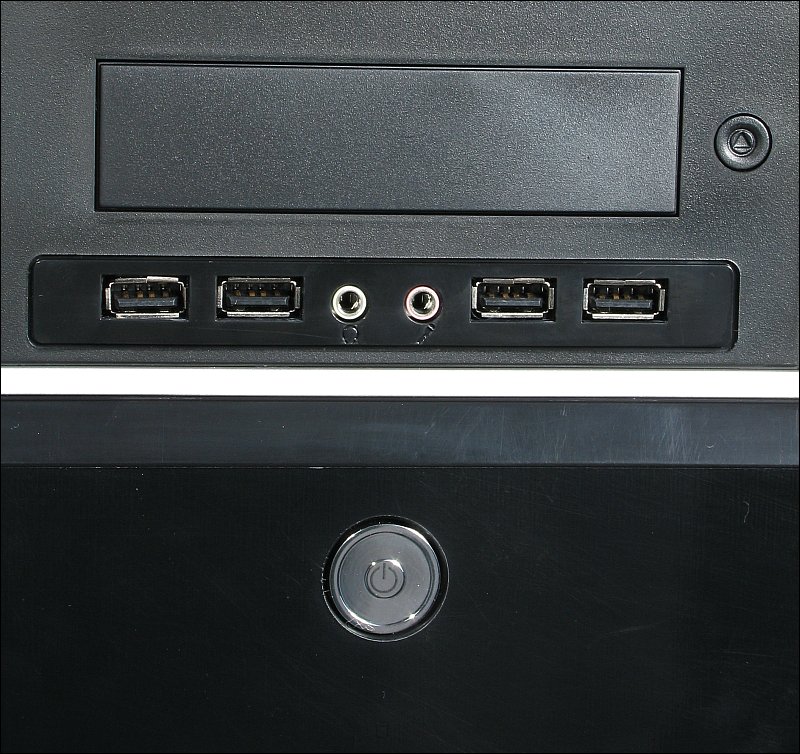
In the following picture, you can see the front of a basic computer. Starting at the bottom and going up, you can see that there is a large round button. That's the power switch. Its used to turn the computer on and off. There are other ways to switch the computer off and I'll cover them later. Above the power button, you can see a row of ports. The four rectangular ports are USB ports. They are typically used with USB flash drives or external hard drives to transfer information onto or from the computer. Between the USB ports are the headphone and microphone jacks. These can be used for gaming headsets. The smaller button to the right of the right-most USB port is the reset button. The reset button should only to be used in the case of a serious crash where the computer freezes. On some machines (machine is slang for computer), the reset button is omitted. If that's the case with your machine, you can reset it by holding down the power button for ~5 seconds.
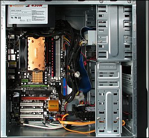
In the front of this computer, there is only one drive. It's an optical drive (term used for CD, DVD and Blu-ray drives - drives that read and write with a laser). Some computers have multiple optical drives but you only need one to burn optical disks. If you copy disks (backup disks, not copyrighted disks, of course), you can rip a copy or the original disk to the hard drive and then copy it back the the blank disk. This is done automatically by burning software if you tell it to copy a disk and it detects only one drive.
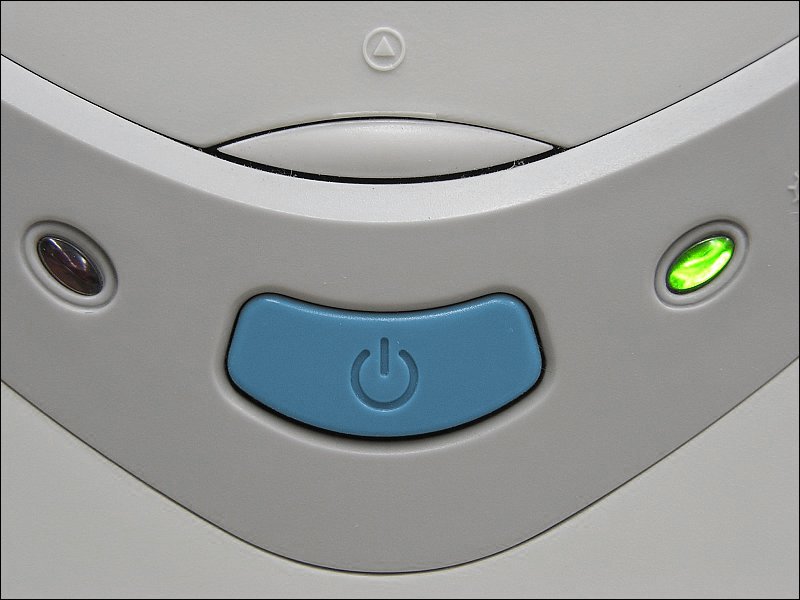
I mentioned the 'power' and 'reset' switches. On new computers, they have somewhat universal markings to indicate which is power and which is reset. In the following image, you can see the front of a computer (a different computer). The power button is marked with the 0/1. The reset switch (the same color as the case here) is marked with a triangle inside of a circle.
Most computers have both 'power lights' and 'hard drive lights'. The power light (power LED) lets you know when the computer is on. If it's on constantly, the computer is operating normally. If it's blinking, it's likely that the computer has gone into either hibernation or suspend mode. The hard drive LED lights up when the hard drive is being accessed or is otherwise active. On the computer below, the lights for power and the hard drive are readily visible. On the one above, the power LED illuminates around the perimeter of the power button. The hard drive light isn't easy to see in the photo and is really only supposed to be seen if the hard drive is active. If you look directly below the power button, about 1/4" above the bottom of the photo, you'll see a vague outline that looks like a short cylinder or pipe. That's the hard drive indicator. In the previous photo, the markings that indicated the function of a button were on the button but that's not always true. Here, the reset button is a bit below the reset marking.
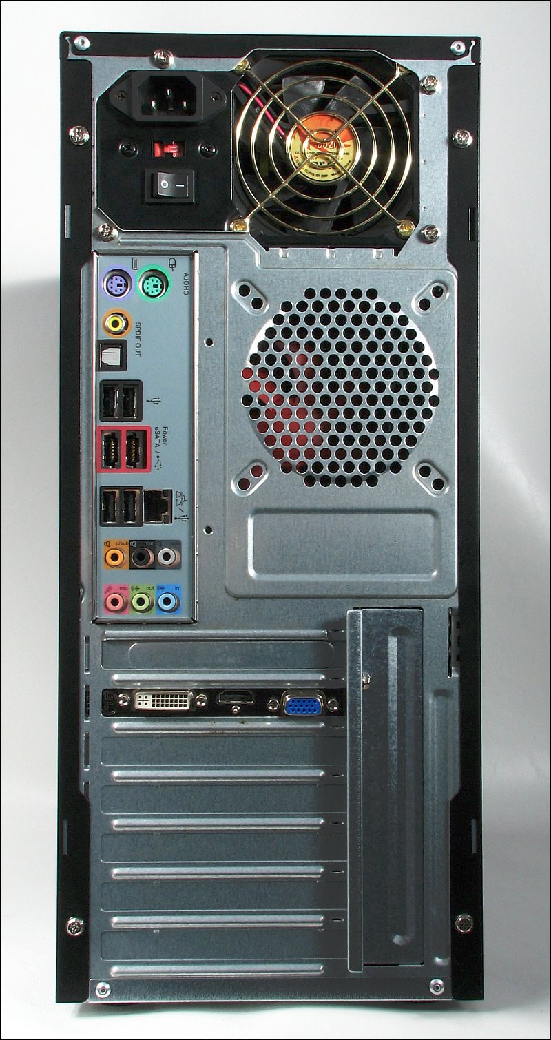
The image below is the rear of the computer that we'll cover on this page. The individual groups of rear panel components will be covered in detail later on this page. This computer doesn't have some of the connectors found on the older computers. If you have an older computer and want to see what the connectors are for, THIS is the old version of this page.
Rear Panel Switches:
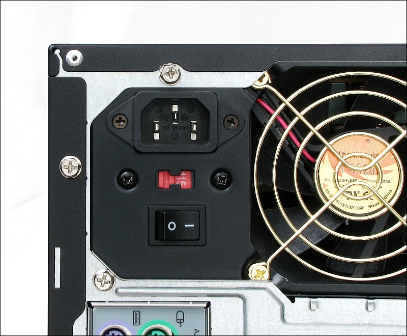
At the top of this computer, you can see where the power source (from the AC mains - the household wall outlet) plugs in. It is plugged into the 'power supply'. The power supply converts the mains voltage 115VAC/230VAC to the various voltages needed by the computer (we'll cover those various DC supply voltages later). On this particular power supply, you can see 2 switches. One is the main power switch. The other is the voltage selector switch. The main power switch completely cuts power to the power supply. Switching this off is essentially the same as unplugging the cord from the power supply. When the end of the switch with the '1' is depressed (as it is below), the power supply is able to power up when asked to by the motherboard. The voltage selector switch allows the power supply to operate with different mains voltages. In Europe and other areas of the world, they use 230VAC (Volts Alternating Current) instead of the 115VAC we have here in the US.
Rear Panel Connectors
P/S2 Ports:
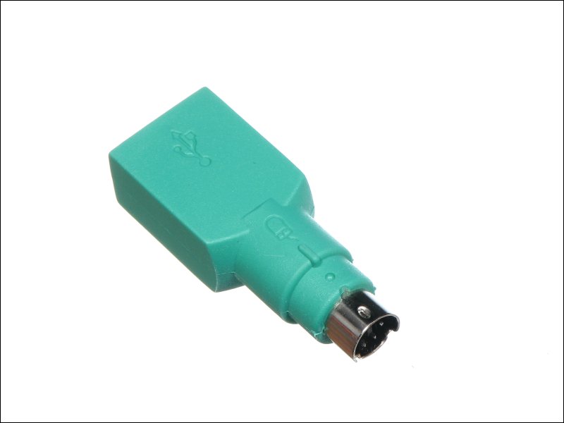
The two P/S2 connectors below are for the mouse and keyboard. Not all new computers have these. Many of the new keyboards and mice have USB plugs. If your mouse and keyboard don't have P/S2 connectors and you want to use these (so that you don't take up any USB ports), you have to use adapters. If you decide to use adapters, you will have to restart your computer after you move the mouse and keyboard to the P/S2 ports. You should also know that some keyboards don't work well on some computers through the adapters.
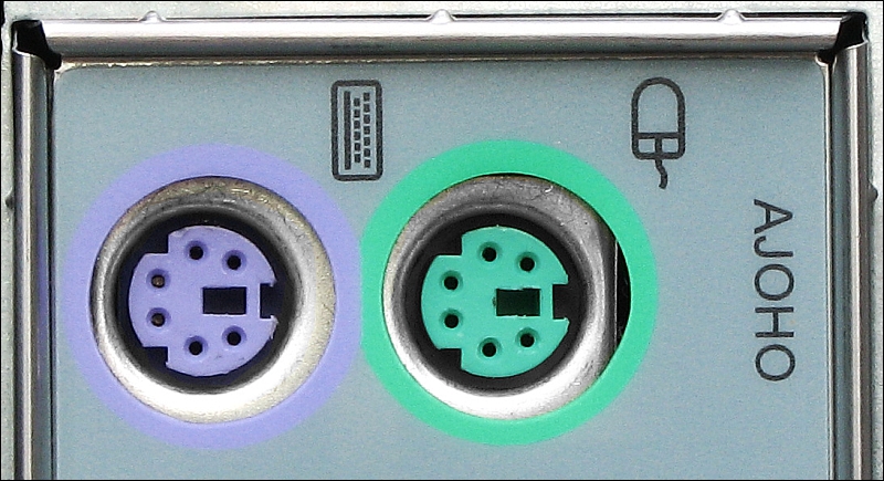
This is a P/S2 connector. This one is for the keyboard (note the keyboard on the connector and the color of the plastic housing). The one for the mouse is green.
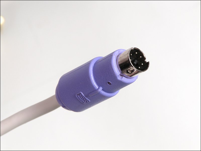
If you have an older P/S2 keyboard and want to use it on a computer without P/S2 ports, you can use an adapter like the one in the following photo.
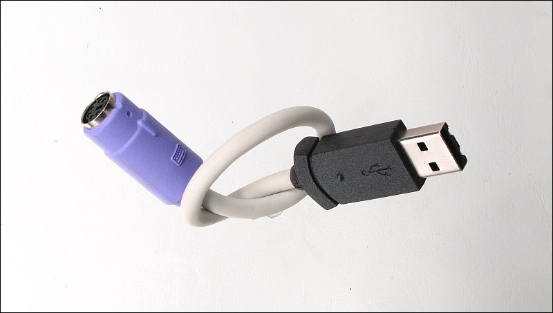
This is a USB to PS/2 adapter.
S/PDIF:
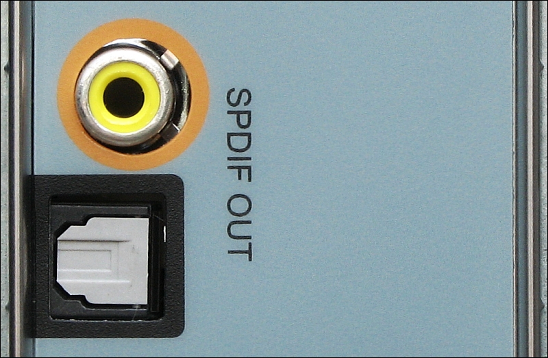
These are digital audio connectors. The one at the top uses a standard phono connector. The one below it uses a Toslink connector. It's an optical output that uses fiber optic cable to transmit the signal to the next component. The gray piece over the port is a door that swings out of the way when you plug the cable in. On this particular motherboard, there is another S/PDIF connector inside the case, near the PCI-E slots. The internal connector is used to send the digital audio signal through the video connectors to make the DVI output function like an HDMI output. You can use an adapter to go from DVI the HDMI.
Above, the connector on the left is covered with a protective boot. The connector on the right is not. The image below shows the bare end of the connector.
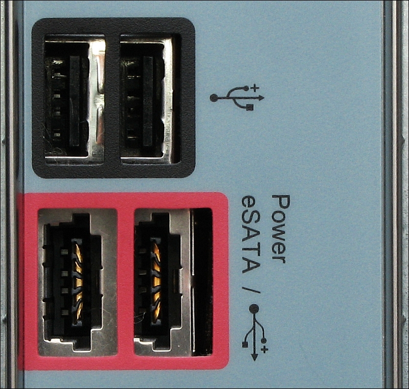
USB 2.0 and Powered eSATA:
The top two ports below are standard USB ports. There are two more lower on the panel and there are 3 more USB headers inside the computer. They can support 6 more USB ports. The powered eSATA can be used as USB ports also but they're designed for an external SATA drive. The eSATA connection is much faster than USB 2.0 so it's favored for transferring large files. USB 2.0 is specified because there is not a USB 3.0 that's faster than USB 2.0. This motherboard doesn't support USB 3.0.
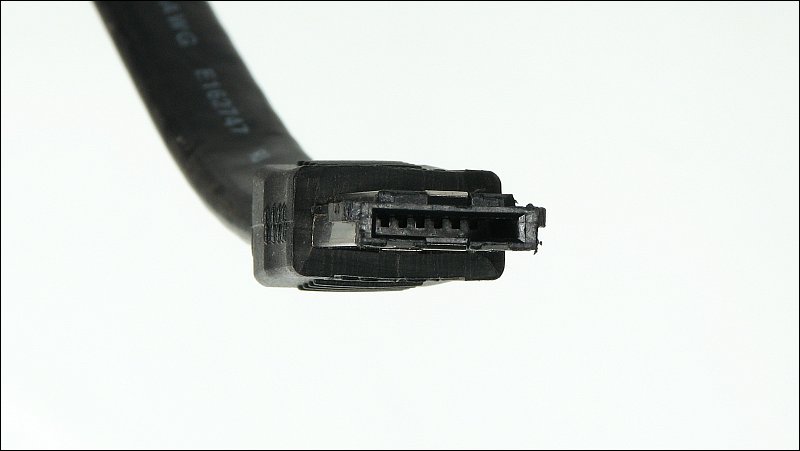
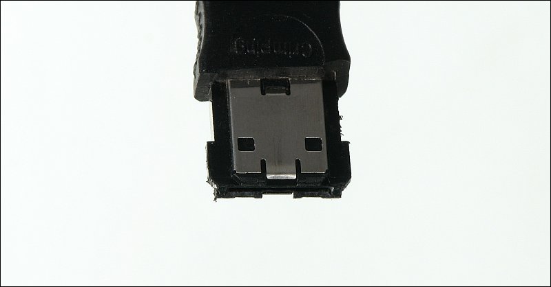
This is an eSATA cable.
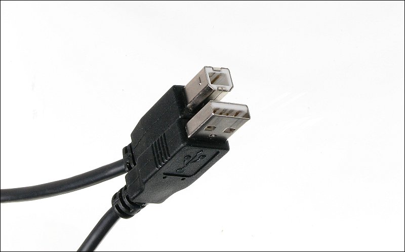
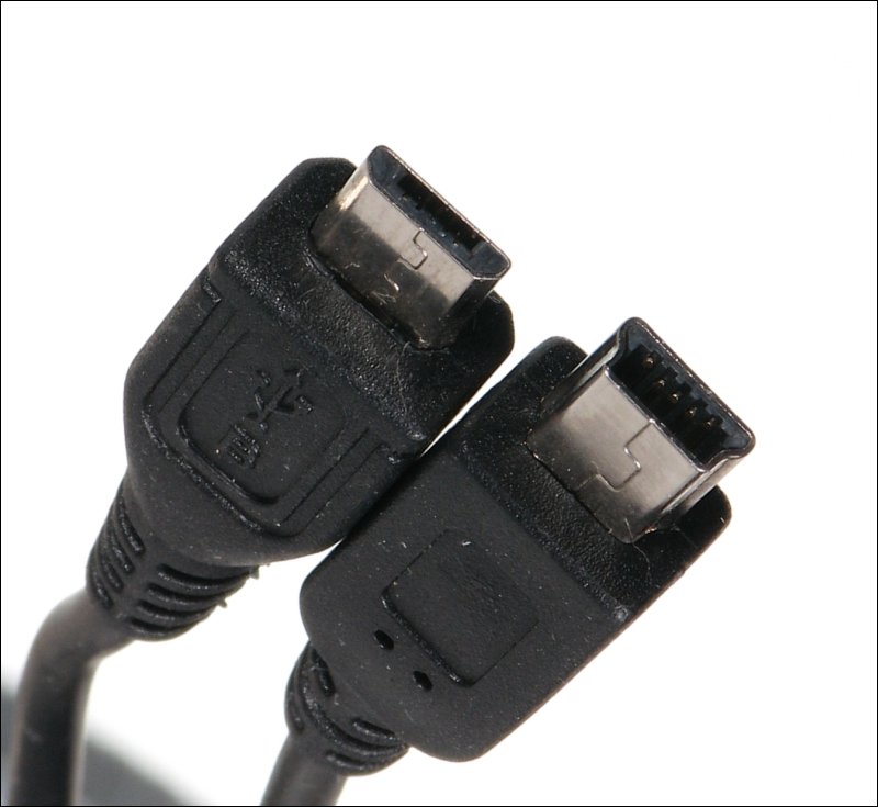
The next two images are all USB cables/connectors. The top photo shows the most common configuration. The top connector is the USB-B connector. The bottom is the USB-A. These are commonly used on printers. The second image shows the mini USB-B and micro USB-B connectors. These are commonly used on cell phones. The 'A' connector is designed to be plugged into the computer or power source (in the case of chargers like those used to charge a cell phone from a power-port adapter in a vehicle). The 'B' connector plugs into the device (most commonly a cell phone).
Ethernet:
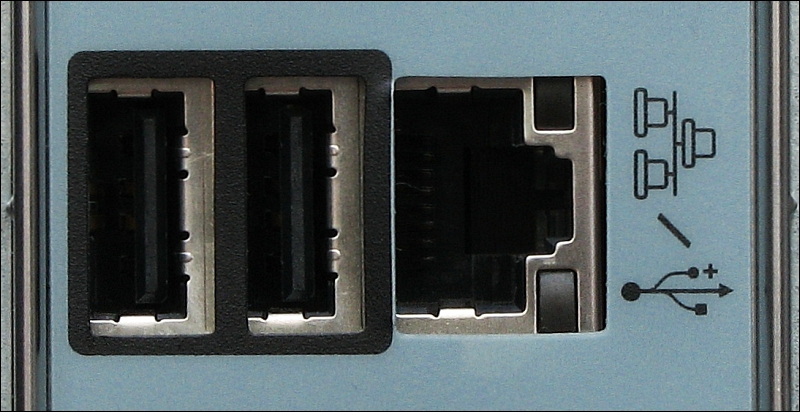
The two connectors on the left are the two USB connectors that were mentioned previously. The connector on the right is the ethernet port. This is where you make the connection to your network or to the internet. The top LED indicates when there is a connection. If it's constantly off, there is no connection/link to the network (cable unplugged/not seated properly in the connector or there is a problem with the network). If it's on solid, there is a connection to the network but no data being transferred. When it's on but blinking, there is activity (data being transferred to/from the network). The bottom LED on the connector indicates the speed of the connection (LED off = 10Mb/s, LED orange = 100Mb/s, LED green = 1Gb/s).
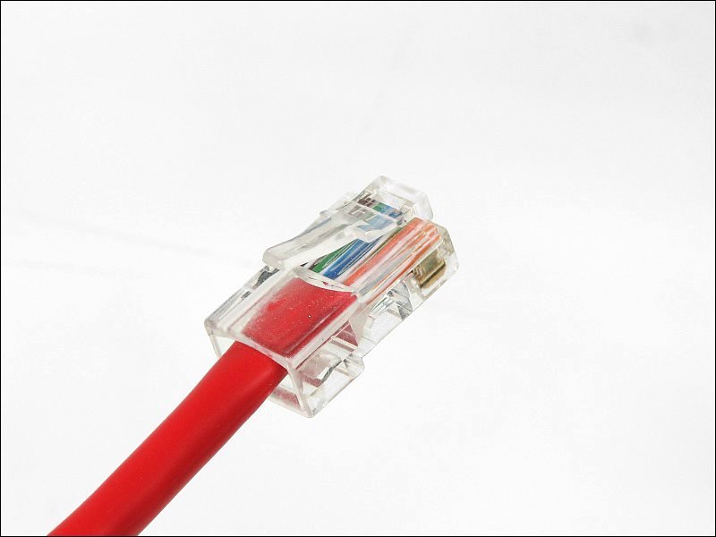
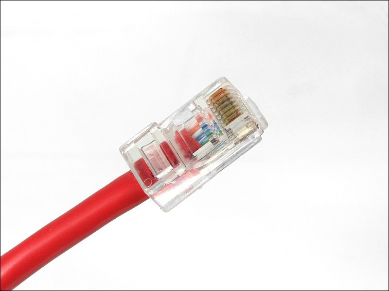
This is what an ethernet cable looks like. The color isn't generally important but sometimes red cables indicate that the cable is a 'crossover' cable and may not work as a link between the computer and the network. The cable construction and the terminals are the same as regular cables but the terminals are wired differently. More information is available on the Networking Hardware page.
Analog Audio:
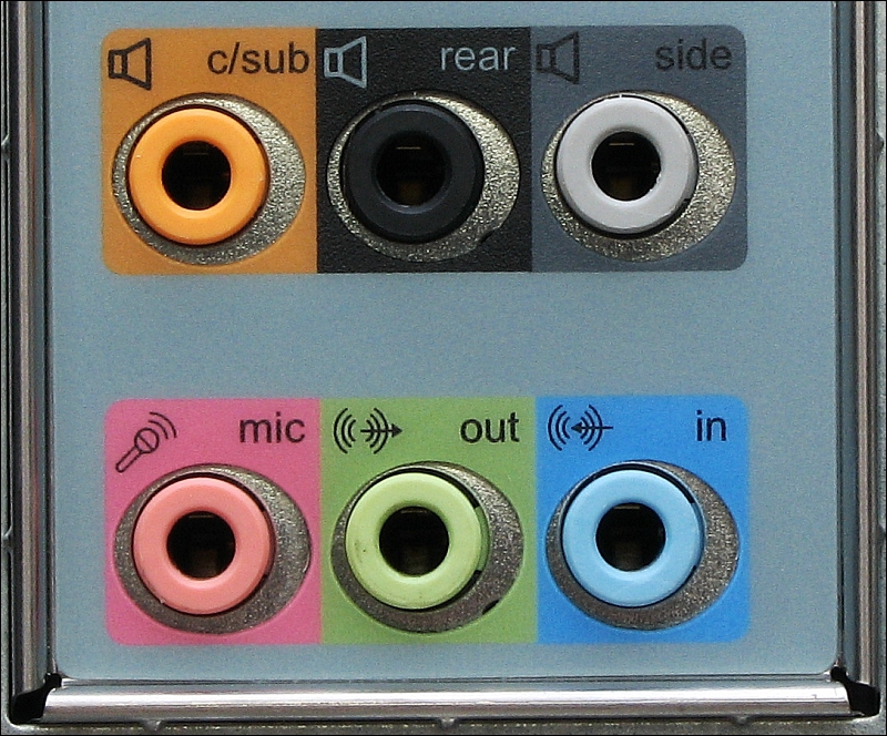
These connectors are for the analog audio inputs and outputs. Each jack is capable of carrying two independent channels. The green (front), black (rear), gray (side) and half of the orange (center channel) produce full range audio. The subwoofer only produces low frequencies. The pink (microphone) supports stereo input as does the blue (preamp level audio input).
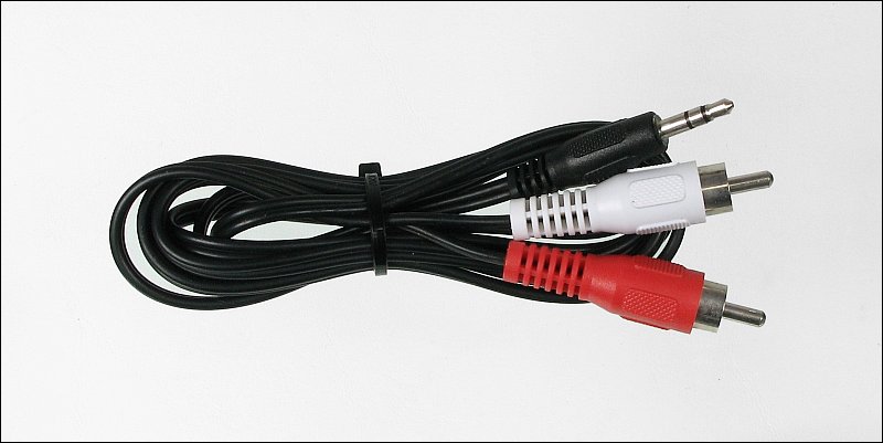
This is one example of the type of cable that you'll use with the analog audio inputs and outputs from the sound card.
Sometimes the integrated audio processor will cease to function (catastrophic IC failure). If this happens, it's not necessary to replace the motherboard. Later in the tutorial, you'll see a discrete sound card that requires installation. For those looking for a simpler solution, a USB sound card is available. These plug into any USB port and you plug your speakers, headphones or microphone directly into the USB device. This is also an option for those who don't have audio connectors on the front of their computer and don't want to have to reach around to the back of the computer to plug and unplug the headphones. When this type of device is plugged into a Win7 computer, it is immediately recognized and and the rear-panel audio is disabled.
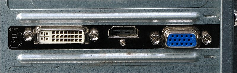
Video:
The next image shows the three video output connectors on the video graphics card. The one on the left is the DVI connector. This connector is designed to send a digital signal to a monitor but also has connections for analog video (same as the blue VGA connector). The middle connector is a standard HDMI port. This port and the DVI port (for video cards capable of doing so) can pass digital audio with the digital video signal. The cards take the S/PDIF signal from the motherboard, either via the PCI-E connector or via a 2-conductor cable.
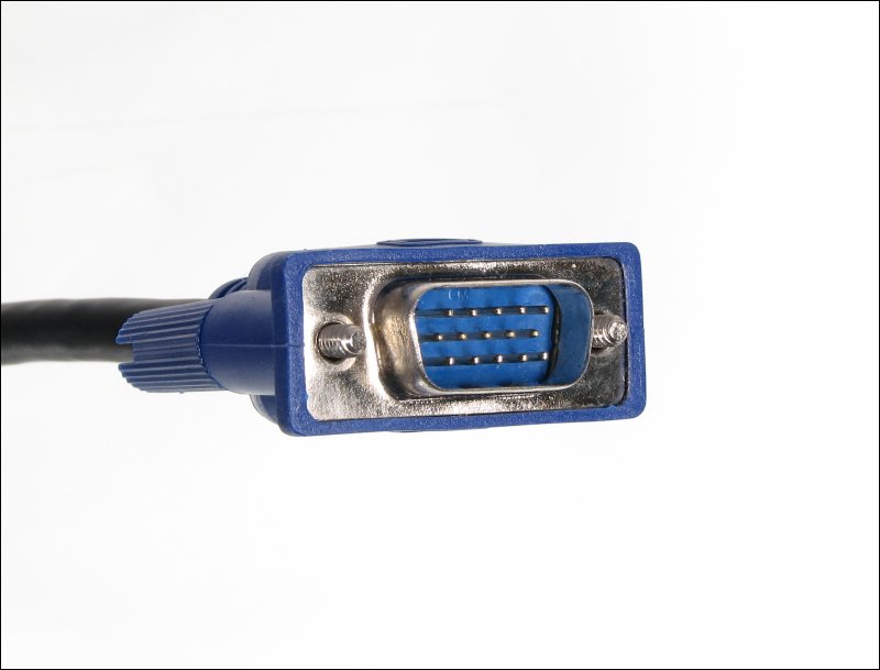
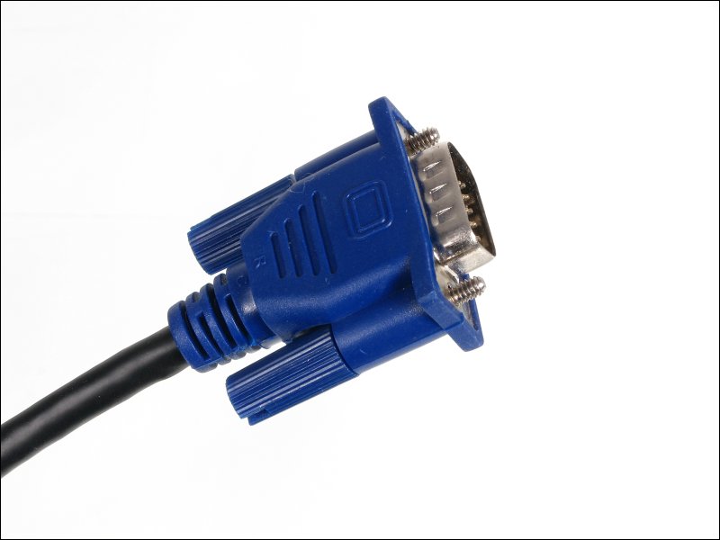
This is what a VGA cable looks like. The cables intended to connect the monitor to the computer will have this type of connector (with the pins inside) on both ends. If it's an extension cable, it will have one connector like this and one connector like the one on the video card.
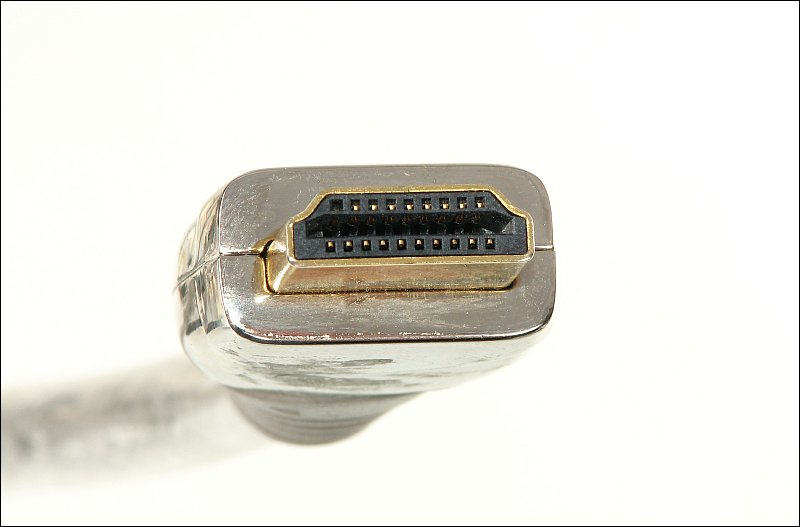
This is an HDMI connector.
|
You May Be Interested in My Other Sites
-
This site was started for pages/information that didn't fit well on my other sites. It includes topics from backing up computer files to small engine repair to 3D graphics software to basic information on diabetes.
-
This site introduces you to macro photography. Macro photography is nothing more than the photography of small objects. It can take quite a while to understand the limitations associated with this type of photography. Without help, people will struggle to get good images. Understanding what's possible and what's not possible makes the task much easier. If you need to photograph relatively small objects (6" in height/width down to a few thousandths of an inch), this site will help.
-
If you're interested in air rifles, this site will introduce you to the types of rifles available and many of the things you'll need to know to shoot accurately. It also touches on field target competition. There are links to some of the better sites and forums as well as a collection of interactive demos.
-
This site is for those who want to install or update their car stereo. It begins with the most basic electronics theory, progresses into basic transistor theory as well as covering virtually everything associated with car audio.
|
|