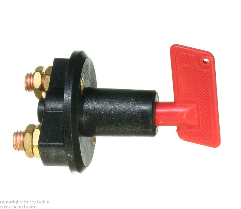
Many people listen to their stereo or use accessories (lights, radio, TV, computers, for those with RVs) without the engine running. This often leads to dead batteries and a vehicle that won't start. A battery isolator will let you completely discharge one battery without discharging the starting battery. Most people opt for isolators that require no action on their part to keep the starting battery from being discharged. This type of isolator is slightly more complex to install than the most basic types of isolators. The most basic isolator is simply a heavy duty switch (generally rated for at least 100 amps of current) that is used to make/break the connection between the batteries. To use a battery disconnect switch like the one below to protect the starting battery from being discharged, you would simply connect it in series with the wire that connects the front and back batteries. In one position, the batteries are connected. In the other, they're not connected. As long as you don't mind having to manually flip the switch and can remember to do so, this is a good, simple solution. In this particular model, the 'key' is removable.
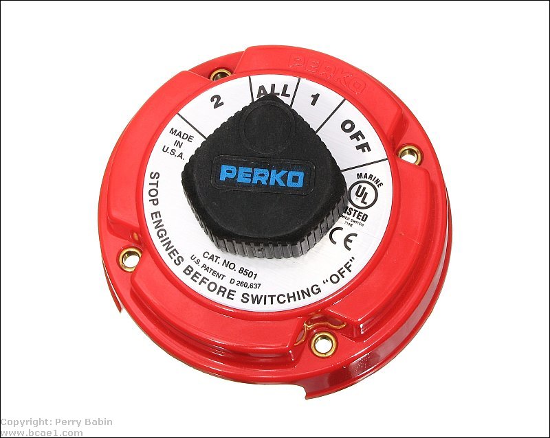
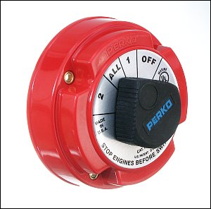
Most of those who use an isolator for marine applications have heard the Term Perko Switch. This is a term used to many of the switches of this type, no matter the manufacturer. This type of switch comes in several configurations. The one below can switch between two individual batteries, both batteries at once or can break the connection to the batteries completely. There are also options to break the connections to the field windings to the alternators but this one doesn't have that option. It's also available with a key to allow you to lock it. The locking version of this switch and the previous switch are good choices for people who have expensive, powerful amplifiers and speakers in vehicles which others are allowed to drive. When needed, the power can be cut to the amplifiers and locked out so that the driver cannot damage the speakers.
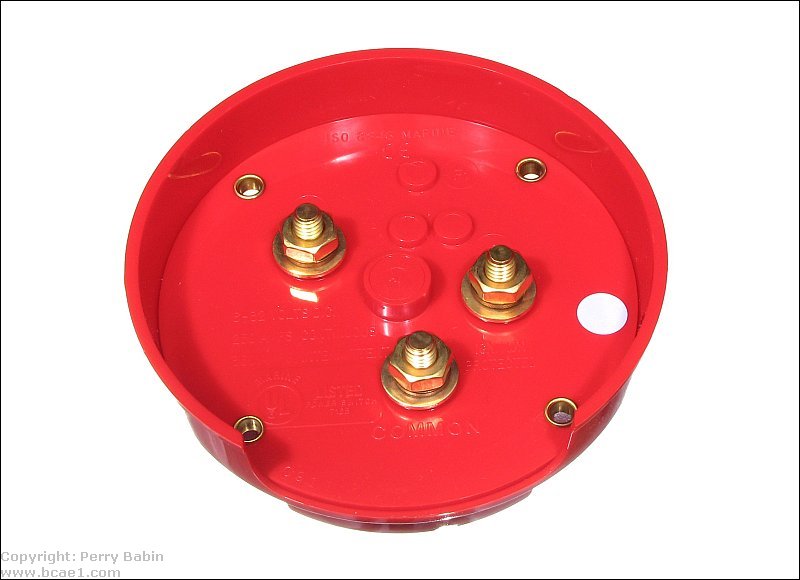
The back of this switch has 3 connections. Terminal 1, terminal 2 and a common terminal. The common terminal is the one that gets connected to the other terminals. In its most commonly used wiring configuration, the common wire feeds the starter for the boat's engine. Terminals 1 and 2 are connected to batteries. If this were used for car audio, the common would be connected to the main power wire that feeds the amplifiers. The engine starting battery would be connected to one of the other terminals. The rear/auxiliary battery would be connected to the remaining terminal. When in the 'ALL' position, all batteries would be connected together and also connected to the main power wire for the amplifiers. When in the '1' position, the amplifiers would be fed from the engine starting battery. In position 2, the amplifiers would be fed from the rear battery. In position 2, the rear battery would be disconnected from the main battery so it could not discharge it but the rear battery wouldn't be able to be recharged. This is the position that you'd use if you want to listen to your system without draining the starting battery. To allow the rear battery to recharge, you'd set it to 'ALL' again.
The switch above is a 'make before break' switch. This means that the contact that's currently engaged will be bridged to the next contact in the rotation before contact broken to the original contact. This is important when you don't want to lose power to the device being powered by the switch. For engine applications, a 'break before make' switch would mean that you may lose power to the computer or ignition system if the switch was changed from one position to another while the engine was running.
Automatic Isolators
There are 2 main types of automatic battery isolators. The diode based type and the relay (solenoid) type.
Diode Based Isolator:
This type of isolator is basically two very high current diodes in a heat sink. The diode based isolator has the advantage of long life and trouble free operation but many of the diode based isolators cause a .4 to .6 volt loss which means that the batteries will not charge to as high a voltage as when they are connected directly to the alternator. The diagram below shows the connection for the diode based isolator. Some diode type isolators have a fourth terminal which controls the current flow through the device or allows the alternator to receive enough voltage to begin charging.
----- Critically Important -----
Flash graphics viewing/use alternatives:
Flash support by most modern browsers has been dropped but that's not the end of the line for Flash.
There is no practical alternative to Flash for the interactive demos/applets/graphics on this site.. Especially when there are alternatives, some simple, some good, some...
Ruffle is chosen by most because they can't imagine using anything but their preferred browser. It works. It's OK but not great. The Flash graphics won't look as they're supposed to but it, generally, works.
The #1 preferred (by me) way to view the site and the Flash graphics is with the Chromium Portable browser and the installation of the older (no time-out) Flash Player files. This was incredibly simple when people knew computers but not today when people only know how to work with their phones.
The Flash Browser is a good option but it's so stripped down that it makes it somewhat difficult to use.
The Maxthon browsers are an option. The v4.95 is the easiest (install and use). V5.3.8 and 6.1.0 require (very) slightly more effort (very).
The Chromium and Maxthon browsers on the page above are 'portable' browsers. They are not installed into your system. They are simply made available for use on your computer. They can be carried around on a Flash drive and used on any computer.
----- Critically Important -----
As of now, from what I've read (I haven't taken one apart), there are 'diode-type' (semiconductor-based) isolators that either use FETs in parallel with the diodes or use FETs in place of the diodes. FETs are Field Effect Transistors and can pass current with less voltage drop than diodes.
Solenoid Based Isolators:
This type of isolator uses large high current relays to control the flow of current. The diagram below shows two solenoids. Solenoid A determines whether the second battery is connected to the rest of the charging system or not. Solenoid B connects the second battery to the distribution block. The second solenoid allows a complete disconnect from the amplifiers for safety. The diodes connected in parallel to the solenoid's coils are used to protect switch A and switch B from inductive kickback when the solenoid's coils are de-energized. The advantage of the solenoid based isolator is that there is virtually no voltage loss across the contacts. The main disadvantage is that the reliability isn't quite as good as the diode based isolator.
The coil of the solenoid will draw significantly more current than can safely be supplied by the remote/power antenna output of your head unit. You should NOT connect them directly to the head unit. You need to use a relay to buffer the remote/power antenna output of the head unit so that the head unit's switching transistor isn't damaged.
In the demo below, click on the head unit to switch it on and off. Click on either side of the toggle switch to change its position. The round green dots are voltage indicators. They are dark when there is no voltage and bright when voltage is present. The arrows indicate current flow through the respective part of the circuit. Switch A allows you to disconnect the main starting battery from the rear battery and amplifiers. This allows you to play the amplifier without fear of draining the starting battery. When switch B is off, the solenoid B is off (disconnected) and you can work on the amplifier's main power wiring without fear of shorting battery power to ground.
NOTE:
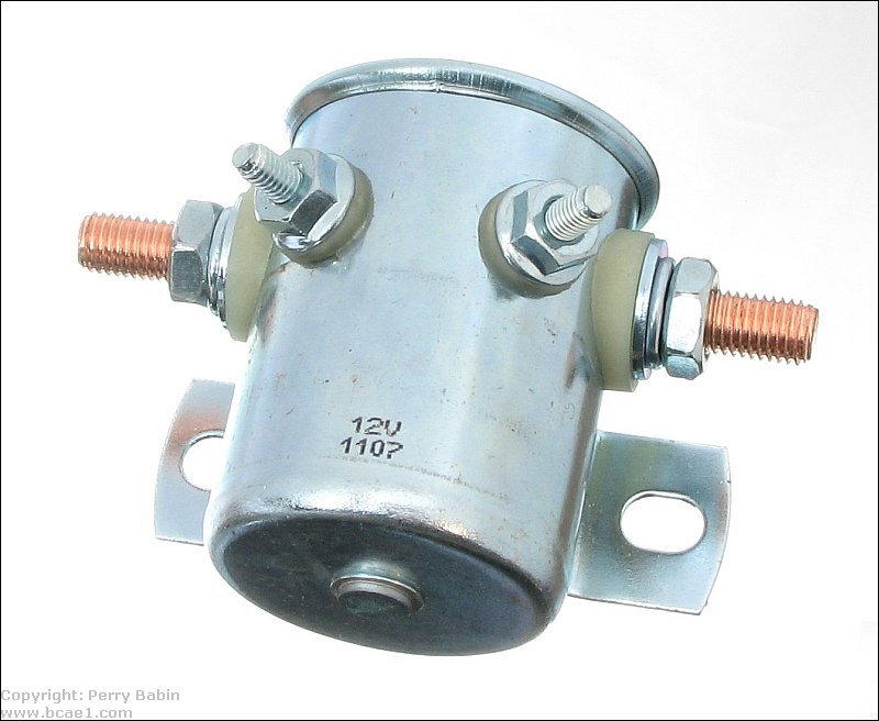
There are 2 types of solenoids. They look virtually identical (like the one below) but are designed for different uses.
Ford Type Solenoid:
If you're familiar with older Ford vehicles, you've no doubt seen the fender mounted solenoid. It's used to make/break the connection from the battery to the starter. This solenoid is designed to pass as much as 400 amps of current but only for a short period of time. The solenoid's magnetic coil has only 3-4 ohms of resistance. If used for continuous duty, the coil will overheat and fail. The low resistance provides higher the contact pressure that's needed to keep the contact resistance to a minimum.
Continuous Duty Solenoids:
For main power switching in car audio, you need a continuous duty solenoid. These solenoids will have approximately 15-30 ohms of resistance across the coil. As you can imagine, this will allow the coil to run much cooler than the starter solenoid mentioned above (although the solenoid will be quite warm after a while). The solenoid I've used is the White-Rogers 70-111224-5. It's available from Grainger or virtually any auto parts supplier. It's rated at 80 amps continuous and can take short periods of higher current flow. I've been using one on my test bench where I draw more than 100 amps through it for 20 minutes at a time and it hasn't failed yet.
Other Isolator Differences
Many people only regard an isolator as a device to prevent draining the starting battery. There are other things to consider as well. Diode based isolators will not allow the rear batteries to help start the vehicle in case the front battery is accidentally drained. If there is enough voltage left in the batteries that switch on the solenoids, the rear battery can assist in starting the battery. With either the diode-type or solenoid type isolators, this can also be accomplished by jumping across the isolator to connect the batteries. Unless the fuses are rated for more than 200 amps, it's often best to let the batteries remain connected to equalize a bit so that all of the current doesn't have to flow through the fuses. Of course, this is for a vehicle in good operating condition, that starts easily but simply has a dead battery.
FET based isolators may not prevent the rear battery from draining if the front battery is drained. Typically, FETs will allow current to flow back through their terminals through the 'intrinsic diode'. Also, if high current is drawn though them in the reverse direction, they may quickly overheat and fail. If you're considering an FET based isolator, ask these questions if these characteristics could cause you problems.
In the case of any of the isolators, if you have a dead battery and a vehicle that doesn't start easily, the best option (if no help is readily available) may be to simply move the auxiliary battery to the engine starting location to start the vehicle.
Adding a second battery without using an isolator:
Some people have good results when they add a second battery to their system. Especially if the second battery is close to their amplifiers. If you want to add a second battery, there are a few things that you should know.
If the battery is inside the passenger (in a hatchback vehicle or in a car with a back seat that folds down), you must use a sealed battery (i.e. Optima). If the battery is being used in the trunk of a vehicle you can use a standard battery but you will need put the battery in a battery box and you will need to provide proper ventilation. Proper ventilation would mean forced air (fan) ventilation from the battery box to the outside of the vehicle. When a standard lead acid battery charges, it produces flammable gases which must be removed from the vehicle to prevent a fire/explosion hazard.
No matter what kind of battery you use, care must be taken to assure that nothing can come in contact with the battery's terminals. I would strongly recommend putting the battery into a plastic battery box with a cover that can be secured onto the box.
The ground for the second battery should be grounded to the floor pan of the vehicle. The floor pan is the main piece of sheet metal that forms the largest portion of most new vehicles. This will provide the best return path for the second battery.
The second battery must be fused. The fuse must be as close to the battery as possible (just as you have on the main battery). All of the power for the system must flow through through the fuses (at the batteries) to protect against electrical fires. The diagram below shows the proper fusing and wiring. The fuse at the main battery must be properly rated to protect wire 'A'. The fuse at the second battery must be properly rated to protect wire 'B'.
Unforseen Problems:
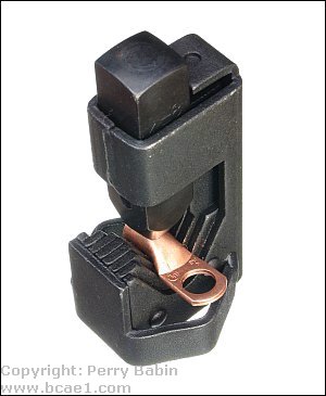
It was stated that the switch at the top of the page is a simple solution... and it is but there are things that you need to consider with any device that requires that you install connectors on large wire. If you're using 4 gauge wire (common in many vehicles), you will need connectors that will fit them. The good quality connectors are made of heavy copper which can be difficult to crimp. Typically, crimp connectors for wire larger than 4g cannot be crimped with standard hand crimpers (like THESE from the Installation Primer page). You either have to use heavy duty crimpers (much larger than hand crimpers - 12-24" long, typically) or a hammer-type crimper (seen at the right - for scale, approximately 4" tall). The hammer-type crimper costs about $30. The hammer-type crimper needs to be used on a solid floor (on a piece of wood on a concrete slab) so it's not practical to use in a vehicle or in an RV. The large, heavy duty crimpers are expensive (approximately $125) so you probably won't buy them. Since at least one end of the wire will be run through the vehicle and therefore not convenient to remove, see if you can rent the heavy duty crimpers before you begin. When searching for these, search for 'lug crimper', not wire crimper.
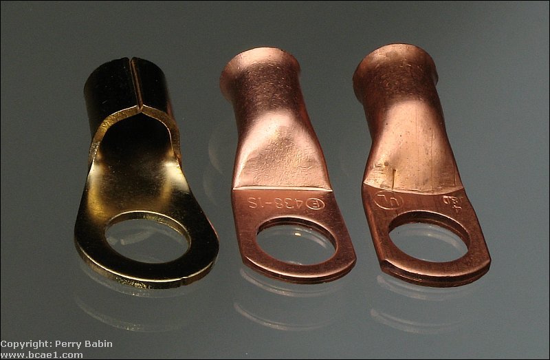
It was stated that the larger lugs are difficult to crimp. This is especially true if you use good quality connectors. For car audio, the leftmost type of terminal is often used. it has a gold plating but otherwise it's not a good choice where it's critical for the connection to be reliable. These don't even have a brazed seam. The opening in the front allows the wire to corrode easily (unless soldered properly). The middle terminal is the type you want to use but is a budget version. The metal around the hole for the stud/bolt is slightly thicker than the one on the left (0.053" vs 0.055) but still not as thick as on a really good terminal. The advantage it has is that the design makes it more rigid which is good if there is a chance that the wire may get pulled on, especially if it's pulled at a right-angle to the surface to which the terminal is bolted. The one on the right is the best of the bunch. The metal on the tab of this one is 0.083" thick. There are even better terminals that are thicker and more resistant to corrosion. They're generally sold as marine terminals. The marine terminals generally look like the two terminals on the right but instead of having bare copper, they're tinned. The tinning increases the resistance to corrosion.
When using a hammer-type crimper, you need to give it a really good whack. If you're using a standard framing hammer, you'll likely have to hit a good quality 4 gauge connector 4-5 times. If you're using a 4lb maul, you will likely still have to hit it at least twice. Of course, when doing this, you need to wear safely glasses.
When buying large lugs, you will find that there are quite a few aluminum lugs. These are typically used by utilities, not the general public. They are good for use on aluminum wire where the crimper is a specialized type that ensures that the crimp is perfect. You cannot solder the aluminum terminals so you need to use copper or tinned copper connectors.
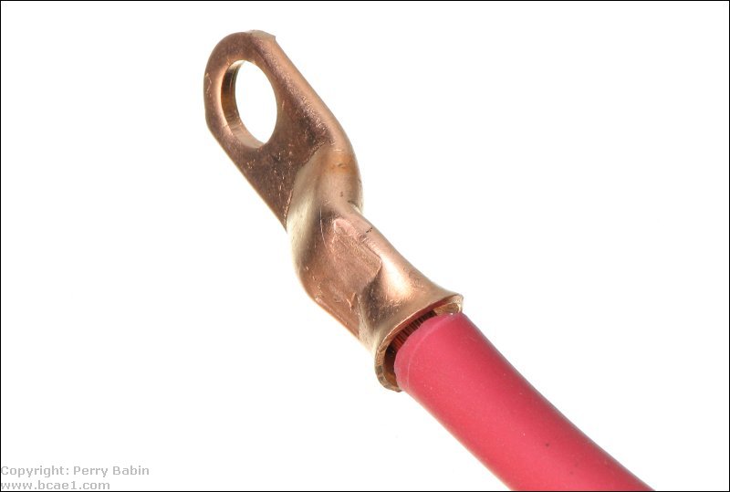
For the best connection, you may also want to solder the terminal onto the wire. When doing this, using a paste flux (specifically designed for electronics, not plumbing connections), can make the solder flow better. Push the wire into the paste before crimping. This will get the flux between the strands instead of just on the outside of the bundle of strands. Radio Shack has paste flux in stock in most stores. When using a torch to solder and paste flux is used, be aware that the flux can catch fire but it's no more significant than a candle's flame. Don't panic. Remove the heat and 'gently' blow it out.
If you intend to solder the connector on the wire after crimping it, when you crimp the connector on the wire, leave a narrow opening between the insulation and the connector to allow you to feed solder into the connector.
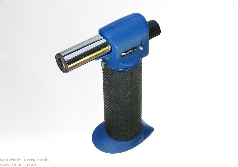
The large connectors are generally soldered with a small butane or propane torch. I highly recommend using a small butane torch like the one below (~6" tall) instead of a larger propane torch.
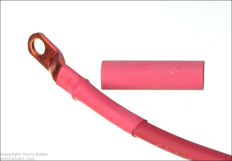
Good quality cable with a neoprene insulation can take quite a bit of heat (but not direct exposure to the flame). Vinyl (PVC) insulation (much more common) cannot take much heat and may melt near the connector. If that happens, you may want to use heatshrink tubing to cover the area that has overheated. Heatshrink tubing is made to shrink to half its diameter when heated to about 120�F. A heat gun works better than a flame for shrinking. It can be done with a torch but great care is needed not to burn the tubing. Below, you can see the heatshrink tubing before shrinking and after it's been heated. When you buy heatshrink tubing, don't be surprised if it's expensive. $3/foot is about what you'll pay for good quality heatshrink tubing.
A few notes...
Soldering isn't absolutely critical but it makes the connection absolutely solid. Crimped connections can fail if not crimped properly and these large connectors can be difficult to crimp properly. If the wire is going to be subjected to high vibration or the vehicle will be used where your life may depend on those connections, you should solder them.
When soldering the large connectors onto the wires, it will take a bit of time and the wire will get hot as much as a foot from the connector. Don't try to hold it in your hand. It's generally easier to solder if you place something heavy on the wire and let about 12-18" hang over the edge of a counter or workbench.
The wire will remain too hot to handle for about 5 minutes after you solder it. After you're finished soldering the connectors, just let it cool for that time.
If you're in a confined space, pay careful attention to where the flame is. It's easy to get distracted when you're examining the connection and you may not be paying attention to where the torch is pointed. When not heating the wire, extinguish the torch. Most have a starter and take only the push of a button to light.
When feeding solder into the back of the connector, if the connector and wire are hot enough, the solder will easily feed in at about 1" of solder per second.
The connectors will tarnish a bit after heating but that's entirely superficial and won't cause any problems.
If you want to protect the connectors from corrosion, you can apply a layer of Goop to the wire and connector (where the heatshrink tubing will cover it) before you put the tubing on. This will seal the connector.
This site was started for pages/information that didn't fit well on my other sites. It includes topics from backing up computer files to small engine repair to 3D graphics software to basic information on diabetes.
This site introduces you to macro photography. Macro photography is nothing more than the photography of small objects. It can take quite a while to understand the limitations associated with this type of photography. Without help, people will struggle to get good images. Understanding what's possible and what's not possible makes the task much easier. If you need to photograph relatively small objects (6" in height/width down to a few thousandths of an inch), this site will help.
If you're interested in air rifles, this site will introduce you to the types of rifles available and many of the things you'll need to know to shoot accurately. It also touches on field target competition. There are links to some of the better sites and forums as well as a collection of interactive demos.
This site helps anyone new to computers and anyone with a basic understanding of computers with a desire to learn more about the internal components of a computer. If you have a computer that you'd like to upgrade but don't know where to start, this is a good site for you.
This site is for those who want to begin racing karts but don't fully understand how the various parts work. It's mostly interactive demos that show how the various parts of the kart work.
Click HERE to visit a friend's new car audio tech site.


 Many people listen to their stereo or use accessories (lights, radio, TV, computers, for those with RVs) without the engine running. This often leads to dead batteries and a vehicle that won't start. A battery isolator will let you completely discharge one battery without discharging the starting battery. Most people opt for isolators that require no action on their part to keep the starting battery from being discharged. This type of isolator is slightly more complex to install than the most basic types of isolators. The most basic isolator is simply a heavy duty switch (generally rated for at least 100 amps of current) that is used to make/break the connection between the batteries. To use a battery disconnect switch like the one below to protect the starting battery from being discharged, you would simply connect it in series with the wire that connects the front and back batteries. In one position, the batteries are connected. In the other, they're not connected. As long as you don't mind having to manually flip the switch and can remember to do so, this is a good, simple solution. In this particular model, the 'key' is removable.
 It was stated that the switch at the top of the page is a simple solution... and it is but there are things that you need to consider with any device that requires that you install connectors on large wire. If you're using 4 gauge wire (common in many vehicles), you will need connectors that will fit them. The good quality connectors are made of heavy copper which can be difficult to crimp. Typically, crimp connectors for wire larger than 4g cannot be crimped with standard hand crimpers (like