
|
| Email Home Page |
|
|
|
|
| Email Home Page |
|
|
|
----- Critically Important -----
Adobe has deemed that the Flash content on web pages is too risky to be used by the general internet user. For virtually all modern browsers, support for Flash was eliminated on 1-1-2021. This means that those browsers will not display any of the interactive Flash demos/calculators/graphics on this (or any other) site.
The simplest (not the best) fix, for now, is to download the Ruffle extension for your browser. It will render the Flash files where they were previously blocked. In some browsers, you will have to click on the big 'play' button to make the Flash applets/graphics visible. An alternative to Ruffle for viewing Flash content is to use an alternative browser like the older, portable version of Chrome (chromium), an older version of Safari for Windows or one of several other browsers. More information on Flash capable browsers can be found HERE. It's not quite as simple as Ruffle but anyone even moderately familiar with the Windows Control Panel and installation of software can use Flash as it was intended.
Many people don't realize that, unless you have virtually unlimited resources, there are going to be trade offs when designing a system. If you want a system to produce a lot of SPL (but have limited power or number of speakers), you'll probably have to concentrate a lot of the acoustic energy within a small band of frequencies. This would allow you to generate the desired SPL and properly impress your friends. It would, however, leave you with a system that would have less than perfect frequency response and marginal performance at the low frequency end of the spectrum. You could design a system that would produce the desired SPL at all frequencies but it would require significantly more power and speakers than the aforementioned system with the narrow peak.
Manufacturers Recommendations:
Enclosure Types: A sealed enclosure will be the smallest (for a given response shape) and will have good low frequency extension but may not have the best low frequency extension. If space is limited, this may be your best choice. A ported enclosure will generally have a better low frequency extension for a given response shape (alignment) but would require a larger enclosure. If you made the enclosure as small as the sealed enclosure but ported it to gain the low frequency response, the output would deviate from the desired flat response. A bandpass enclosure can sound good and give you a flat response but most of the generic bandpass enclosures are not designed for a flat response. They are designed to impress you in the stores. This means that they are built to produce a large peak at some frequency near 60hz. These enclosures will work well with something like rap music but generally won't sound good with other types of music. If you use a bandpass enclosure, it should be designed specifically for your speakers. If you're building your first system, I'd recommend a sealed enclosure. It is the simplest enclosure and will be the easiest to get right. A sealed enclosure only needs to be the right size and well sealed.
As you already know, for speakers (especially woofers) to work properly, they must be in the proper size enclosure. The manufacturer can give you the required enclosure volume but can't give the exact dimensions of an enclosure that will work in all vehicles. So that you can build an enclosure of the proper size for your vehicle, this page will explain how you calculate the total volume of the enclosure.
Magic number:
Square or Rectangular Enclosures:
Warning: If you want to compensate for the volume taken up by the woofer, you can use the following approximations. Keep in mind that these are for 'normal' woofers. If you're using a competition woofer with a huge frame and magnet structure, refer to the manufacturer for the actual displacement volume of the woofer. Even if you're not using competition woofers, most high quality manufacturers provide this spec in the woofer's datasheet.
Use this calculator to determine whether your speaker is best suited for use in a sealed or ported enclosure. In the calculators that follow, if you are using internal measurements, make sure the wood thickness is set to '0' (zero).
Triangles without right angles:
Combination Enclosures:

Updated June of 2022.
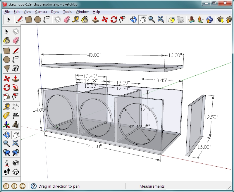
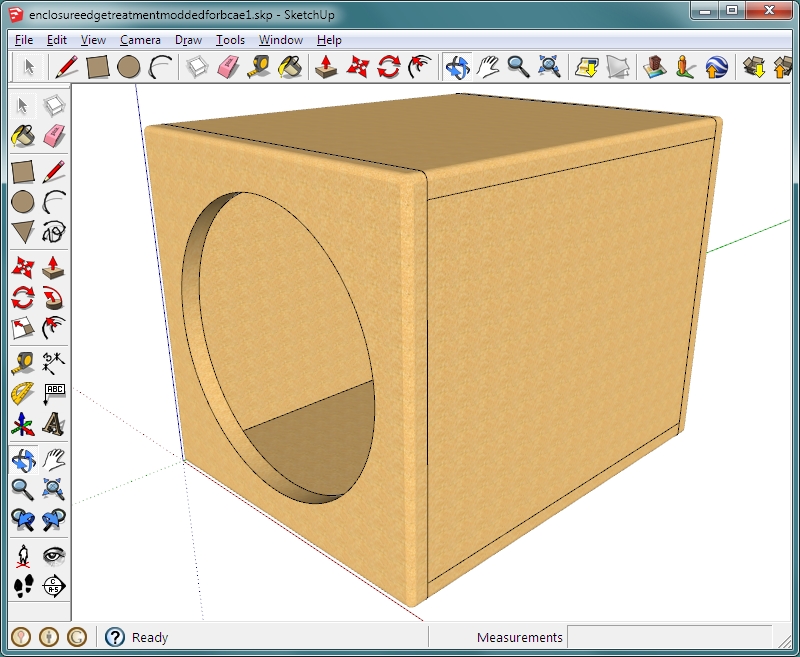
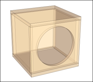
Before you build an enclosure, you may want to draw it out. This can help prevent making mistakes when cutting the various panels. It also allows you to double-check measurements, which can be taken directly from the scale drawing. For those who are willing to take a few minutes to read through a basic tutorial, you will be able to use Sketchup (a free 3D drawing/modeling application). It's on one of my other sites (asos1.com). The tutorial page is #10 in the directory. The following show enclosures drawn in Sketchup. For those willing to take the time to learn the software, it could prove at least moderately profitable. There are a few people getting paid to draw enclosures on the various car audio forums. Even if you only charge $5 each, you can make an extra $15-20/hour in your spare time. Most enclosures can be drawn in 15-20 minutes.
Borrowing Tools: I'd suggest that you NOT borrow tools from people who earn a living with those tools. If you borrow a circular saw from someone who needs it to make a living and you damage it, you could cost them quite a bit in lost income.
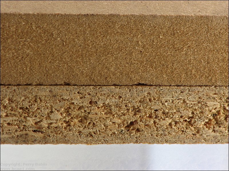
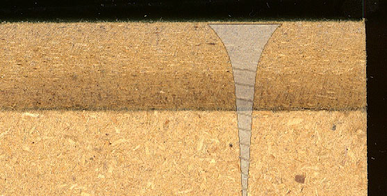
MDF: The image below shows the cut edge of MDF (top) and particle board.
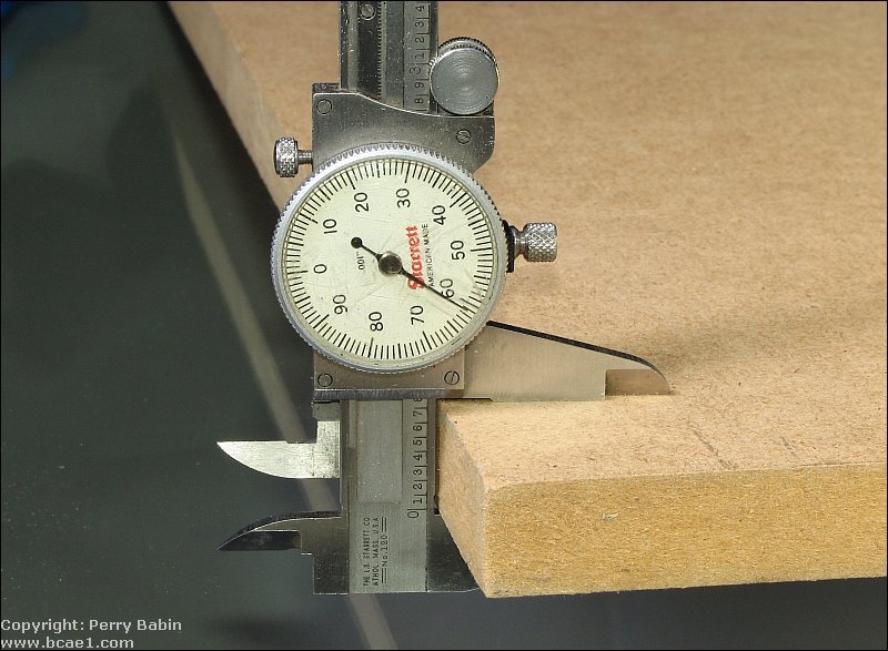
 When cutting the pieces for the enclosure, you may be tempted to simply use the thickness specified by the manufacturer. In most cases, MDF is thicker than the stated thickness. The following is 3/4" MDF. It should read 0.750. It reads 0.761 in the dial indicator. If you make the cuts assuming that the MDF is exactly 3/4" thick, the pieces won't fit properly. For most newbie box builders, this isn't a concern because the cuts will not be very accurate but if you're using good tools (table saw with a solid fence) and are careful when measuring and marking, this will make a big difference.
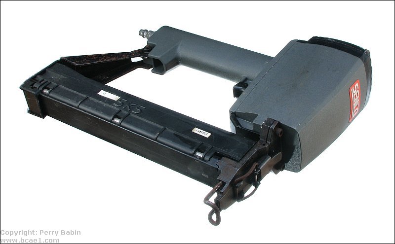
Stapler:
Adhesives: You've likely heard that the glue holds strong enough that you could remove the screws and the enclosure would remain strong. It's true that the glue is that strong but the glue is only bonded to the surface. For material like MDF (which is essentially highly compressed layers of cardboard/paper), the surface can be pulled up fairly easily. The screws prevent this from happening and add significant strength to the enclosure. If you make a slight mistake when cutting (often happens when using a circular saw without a guide) and there is a small gap that wood glue won't fill, you can mix sawdust and wood glue and use that to fill the gap. The old type silicone adhesive/sealant has acetic acid which is released as the adhesive cures. This acid will corrode speaker baskets if the speakers are reinstalled before the silicone has completely cured. If you have to use silicone, use 'Silicone II". The best way to make sure the enclosure is sealed is to make good quality cuts. It will take less time to make good cuts than it will for the sealant to dry/cure (24 hours). If the cuts are good enough, you won't need any sealant other than the wood glue. Some people use liquid nails type adhesives to seal the joints but the solvents in construction adhesives can soften the adhesives used on some speakers (which could lead to premature speaker failure if the speakers are installed before the adhesive has dried completely). You should also realize that the fumes may well be flammable (and may be explosive when in a confined space). If you have a loose speaker connection on the speaker terminals, you may have a fire/explosion hazard if the speakers are played before the solvent has fully evaporated. Liquid nails is another substance that you don't want on your skin. If you remove it immediately with a solvent like acetone, you can get most of it off. If you let it dry, expect a week before it's completely gone. While we're on the subject of solvents... Too many people use gasoline (petrol) as a solvent to remove adhesives and such. This is IDIOTIC. If you ever see a gasoline fire, you'll understand why. Gasoline doesn't burn like it does in the movies. Gasoline burns very quickly and very hot. Do NOT use gasoline as a cleaner.
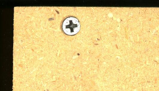
This photo shows what the screw heads look like when they are countersunk into the face of the board. The counter bore recess was simply drilled to approximately 1/8 inch in depth at the center of the hole. Counter-sinking greatly reduces the chances of breaking out the edge of the board and it produces a better looking enclosure. The holes were also pre-drilled with a 3/32" drill bit to prevent splitting the wood.
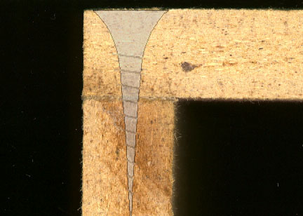
 This is the end of the board where the screw holes were pre-drilled. You can see that the wood didn't split.
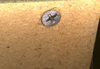
 This is the what the screw looks when you don't countersink the screw holes.
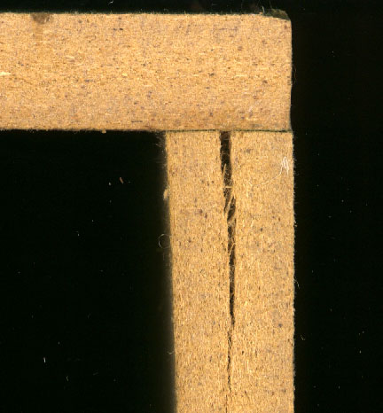
 This is what can happen when you don't pre-drill the holes.
 This is what the edge of the box should look like. There should be no gap between the two pieces of wood. The strength of the enclosure depends largely on the accuracy of the cuts. Remember, wood glue is not designed to fill large gaps.
 When building an enclosure, if you don't have a lot of experience, you probably won't make perfect cuts. If you have a choice of making the panels slightly shorter or longer, make them slightly longer. In the image below, you can see that the one that's slightly longer extends beyond the face of the enclosure slightly. This is correctable with either a belt sander or a router, using a bit with a guide bearing or bushing (the first router bit below is one example).
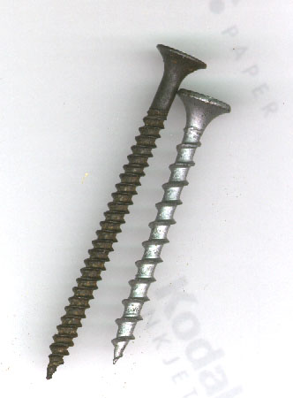
If you have trouble getting straight cuts, use as many of the factory edges as possible. If, for example, you can have a panel with one factory edge and one bad (poorly cut) edge or one with two bad edges, cut it so that you use the factory edge. A belt sander was mentioned previously. If you've never used a belt sander, you should understand that it's not as easy to control as an orbital palm sander. When using a belt sander, you must have a good grip on it and be on good footing. If you're slightly out of balance, it can pull away from you. You should also understand that it can cut FAST. With a 40 or 80 grit belt, it can cut 1/16" off of your enclosure (or your skin) before you can react. It's been suggested that you clean-up the glue that's displaced when you screw the panels together. This is especially important if you're going to have to sand the enclosure. The glue will clog the sandpaper and make it useless. This can happen with a new belt the first time you try to sand over an area with a lot of glue. You can sometimes clean the paper with a wire brush but the belt won't work as well and will likely have to be replaced. When you go to buy belts for your sander, you'll need to know the size. 3" x 24" is common but there are other sizes. If you don't kneed, bring the old belt with you. The size is sometimes on the belt but it's generally worn off by the time the belt needs to be replaced. The image below shows two different types of drywall screws. The coarse threaded screw is, in my opinion, a better screw for box building. They go in more quickly and don't strip out as easily but may be more likely to cause the wood to split. Try both types and use the one that works the best for you. I used the coarse threaded screws in the previous images. The galvanized screw below is a #6 drywall, and is 1 5/8 inches long (the preferred screw for building enclosures).
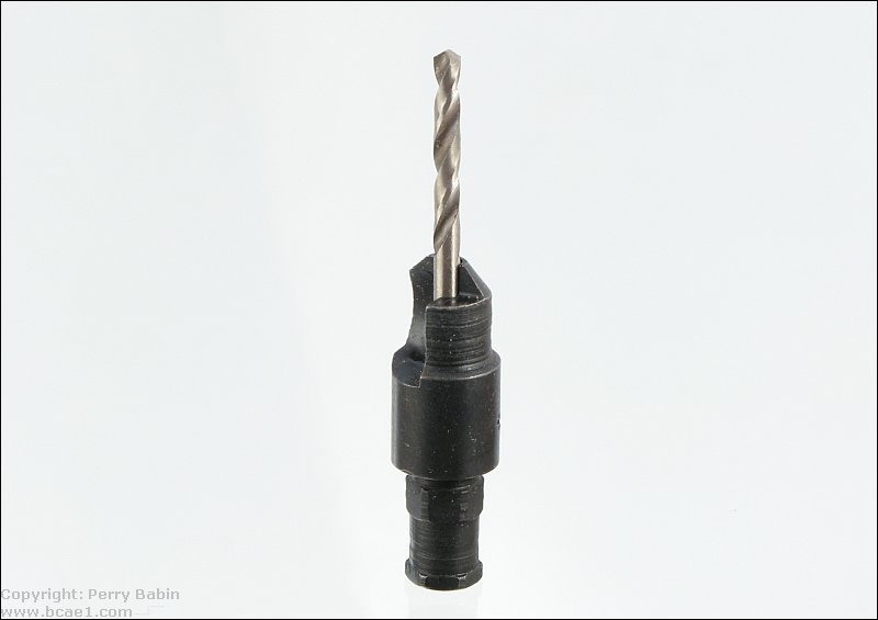
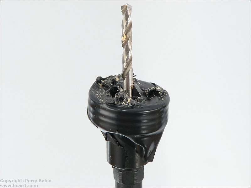
 When using screws with either phillips or Torx head screws, you need to make sure that you have a bit that fits properly (preferably one supplied with the screws). You also need to keep the bit inline with the screw. If you have a bit that fits properly and is inline with the screw, there is virtually no chance for it to slip. If it does slip, it will likely damage both the bit and the screw. If the bit is damaged, it may make it difficult to finish the job. It's good to have extra bits on-hand. The following two images are of a countersinking bit. The first is the bare bit. When using the bit in this way, it's difficult to get consistent depth. The second image shows the bit with several washers taped to the bit. This make is really easy to get consistent depth on the holes.
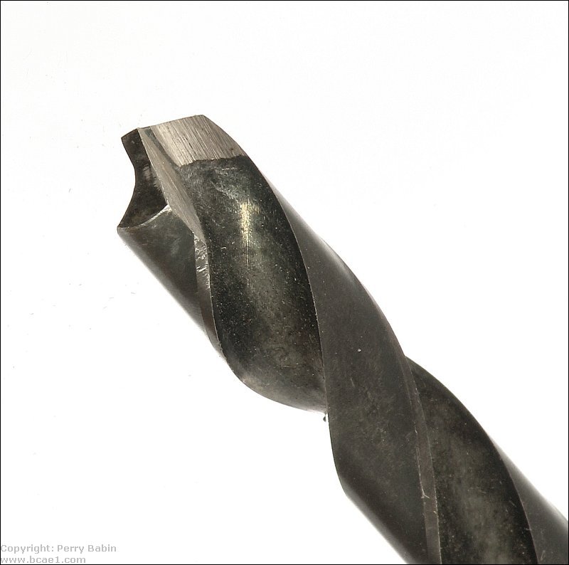
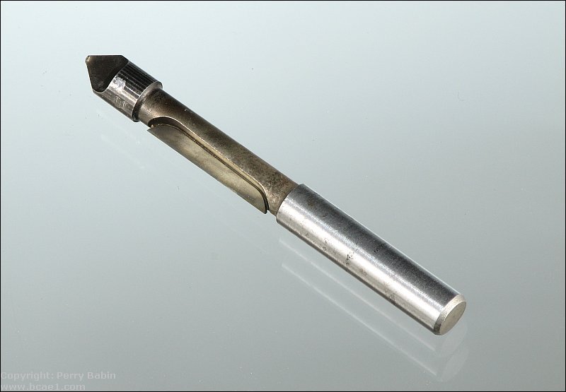
 It's possible to use a drill bit to countersink the heads (after pre-drilling with a 3/32" bit) but you must be very careful. Most drill bits tend to pull themselves into the material being drilled. It's very easy to go too deep when using standard twist type drill bits. Using bits with a flat cutting edge will allow you to drill without a risk of the drill bit un-intentionally going too deep. The bit below is a standard drill bit that's been ground to have a flat cutting edge.
Cutting Holes with a Jigsaw: When selecting a blade to make the cutout for woofers, you should choose a blade that's relatively deep (front to back). This will make the blade stiffer which will help keep the blade from deflecting to the side (which causes the sides to be bevelled instead of square). The blades that are thin from front to back are better for cutting tight curves but you don't need that for cutting woofer holes. A blade with larger teeth with significant side-set will cut faster but may make a rougher cut (especially if you try to cut too fast). If you're not on a tight budget, buy a multi-pack of blades so you can try several (on scrap material) to see what works best. A standard jigsaw simply moves the blade up and down. More advanced jigsaws have an 'orbit' setting. There are typically 3 orbit settings and one straight setting. The orbit feature makes the tip of the blade follow an oval path instead of going straight up and down. When making rough cuts, the orbit setting may be the best option but it's not generally the best option when making precision cuts. When using the orbit setting, the area in front of the blade will typically get chewed up pretty badly (tearing away the line that you're following). When using the non-orbiting setting, the line will remain largely intact until the cutting edge of the blade reaches it. Practice on a scrap piece of wood to see which works best for you. If you don't have much experience with a jigsaw, set the jigsaw to the straight setting. Many jigsaws have a variable speed control. It's generally not necessary to use the jigsaw at full speed. If you have a sharp blade, the saw will be able to cut more quickly than you can react if the saw begins to go off of the line. Using a slower speed will make it easier to react before you go too far off of the line. When marking the hole layout, you'll want something that will make a ledgible line in one pass. A red fine point Sharpie marker works very well. You'll need to go slow when marking (so the color remains intense) so you only need to make one pass. It's difficult to make additional pass precisely on top of the first pass which leads to multiple lines or a thickened line.
Cutting Holes with a Router: Using a jigsaw to cut holes for speakers works well enough for most people but if you want perfect holes, you have to use another option. For those who think that they can cut perfect holes with a jigsaw, you've never seen holes cut as described in this section. There are two common ways to cut perfect speaker holes in the baffle of a speaker enclosure. Some people use a circle cutting jig that mounts onto the router. These work well and can work for cutting holes in baffle boards but you have to be very careful at the end of the cut if you're cutting the holes on an assembled enclosure. If you have to cut a lot of holes the same size, I'd strongly recommend that you use the circle cutting jig to make a template and use the template to cut the holes in the baffle of your enclosure.
If you're going to use a template to make the holes in the enclosure, you don't need to buy an expensive circle cutting jig. You can make one in about 10-15 minutes and since it's only going to be used a few times, it doesn't have to be anything special. It simply has to attach to your router base-plate and allow you to have a place where you can drill a hole to set the diameter of the hole that it will cut.
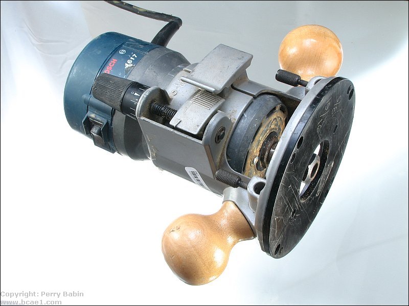
Router Basics: If you don't have a router, you should try pawn shops as a cheap source of routers. Before buying from the pawn shops, call the ones near you to see what models they have and get their prices. Then check the prices in the regular outlets. It's possible to get a good deal in a pawn shop but many pawn shops charge near-retail prices for used items so it pays to do your homework before buying from them. Of course, this doesn't only apply to routers. It's only mentioned here because it's the tool that you're least likely to have. There are two different types of commonly available bases for routers. One is an adjustable, fixed base. This allows you to make adjustments to the cutting depth before the router is powered up but you can't change the depth of cut while the router is in operation. The router below has a fixed base.
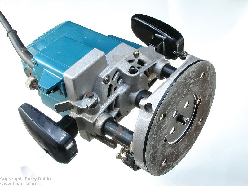
 The second type of base is a 'plunge' base (see below). This allows you to start the router without the bit protruding through the base. After the router is up to speed, you plunge the bit down into the material that you need to cut. The plunge base is required to use the circle cutting jig. You can use a router with either type of base when you have a template.
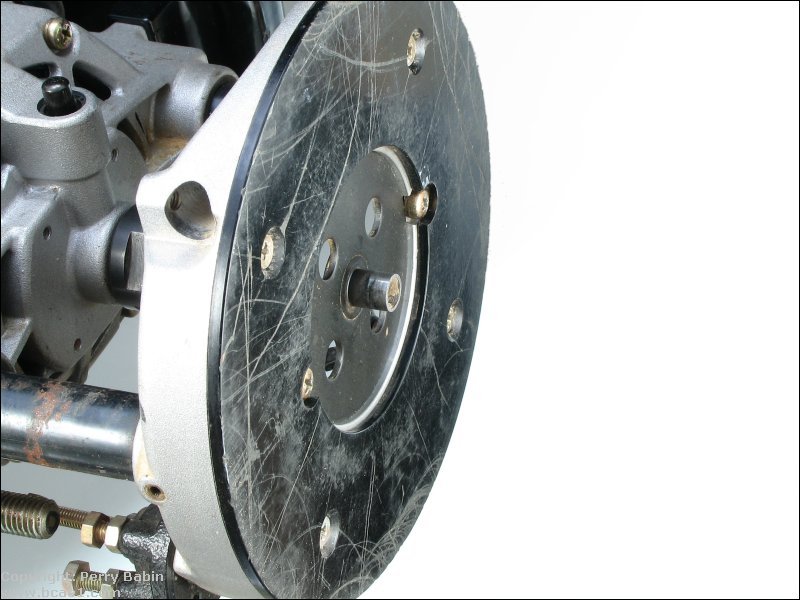
 This shows how the guide bushing fits onto this particular router. This one is held in the base by two screws. Others are held in the base by a nut on top of the base. The outside diameter of this bushing is 3/8" (for a 1/4" cutting bit). This is why the speaker template hole has to be slightly larger than the actual speaker hole. The router's bushing diameter will dictate the actual size differences between the template hole and the speaker cutout hole. The bushing is installed after the router is removed from the circle cutter jig (for those circle-cutting jigs that mount rigidly to the router's base).
 When using the guide bushing with a template, there are a lot of choices for router bits. Cheap bits are made of 'high-speed steel'. HSS bits will not last for more than a few cuts in MDF or particle board. If you buy an HSS bit to cut the holes in MDF for two 12" woofers, expect to burn through the last part of the second hole because the bit will have dulled. There are three basic types of router bits. The first is the high-speed steel bit. They are the cheapest but also dull more quickly than the others. There are solid carbide bits. Carbide is much harder than high-speed steel and will hold a sharp edge much longer than a high-speed steel bit. They are also the most expensive of the three types. The third type has a steel body with a carbide cutter brazed to it (below). Steel bits with carbide cutters are typically cheaper than solid carbide bits and last about as long. If you're searching for a bit similar to this one include the following terms: plunge pilot panel router bit 1/4"
 Using a large router, you can easily cut the entire thickness of 3/4" MDF in one pass. If you intend to do this, you need to make sure that the cutting edge is at least 3/4". The two most common choices for 1/4" diameter bits is 3/4" cut and 1" cut. If you have only a smaller router that doesn't have the horsepower to cut 3/4" material in one pass, you can cut in 2 or 3 passes, cutting deeper with each pass. Using a template or a good quality circle cutter will produce a perfect opening, even after multiple passes.
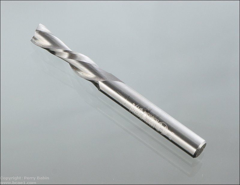
Note: For bits that cut straight slots, there are two main types. One is a bit with a straight cutting edge (like the one above). The other type is a spiral bit (below). It has a spiral cutting edge. The spiral bits are used where the edge finish needs to be nearly perfect (for cutting soft metals or plastics, like acrylic). For cutting MDF, straight bits will cut well enough. If you want a spiral bit, the Bosch 85903MC and the 85911MC work well and are readily available for about $20 each.
 Spiral bits come in two styles, upcutting and downcutting. The upcutting bit pulls the waste material up and out of the slot. The downcutting bit pushes the waste material down. If you're using this to cut the holes in a baffle board that's mounted onto the enclosure, a downcutting bit will throw most of the sawdust into the enclosure (which can be easily vacuumed out). The upcutting bits are better when you're making a cut that doesn't go completely through the material or when you have a vacuum attachment on the router. All of the bits mentioned/shown here are 1/4" cutting bits (they cut a 1/4" slot). Larger bits take much more horsepower to turn and make more of a mess (more sawdust). Smaller diameter cutters are typically easier to break.
Installing the Router Bit:
Stuck Router Bits: Some routers are more stubborn. When you loosen the collet nut, it pulls the collet out of the spindle and, when all is right, the collet remains free in the nut. In some routers, the collet gets wedged in the nut and the entire nut/collet/bit assembly has to be removed to remove the bit. When this happens, place the assembly on a solid surface. Place a deep socket (the type used with a ratchet) over the bit. It must be completely clear of the bit and must rest solidly on top of the collet. Tap the top of the socket to force the nut down. When the nut is free, the bit should pull out freely. It's important that you not leave router bits in the router for long periods of time. They can become stuck and be very difficult to remove.
There are quite a few commercially available circle cutting jigs. The Jasper circle cutting jig is probably the most well known. Most of these jigs mount rigidly onto the router base. The following 'home-made' jig has a hole for the router guide bushing that's the same size as the outer diameter of the bushing. This keeps the router and jig together instead of screws and it allows the router to rotate freely on the jig.
 The following image shows a more typical jig that mounts to the router rigidly. If you buy a jig like this, make sure that it has holes that will match the holes in your router base. Some routers have 3 holes and some have 4 holes in the base. Some jigs are made for either 3 or 4 hole routers but not both.
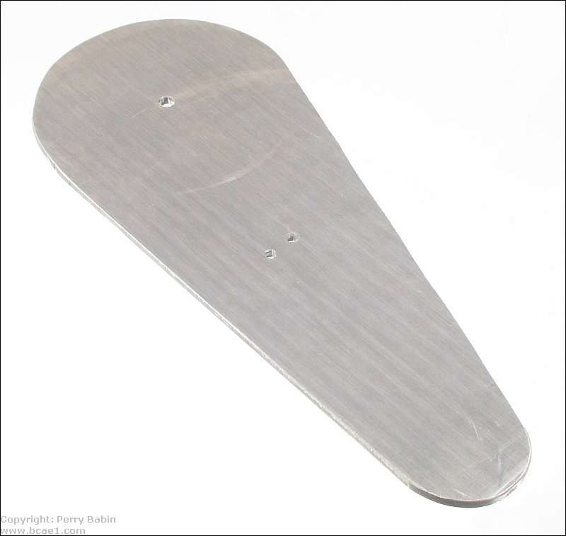
Click HERE to make this applet fill this window. It's not important that the pivot-point holes in the circle cutting jig are through the center-line of the jig. All that's important is that the hole is the proper distance from the bit. When making a template, the hole in the template must be slightly larger than the required speaker cutout to compensate for the diameter of the guide bushing. The hole in the template must be the diameter of the speaker cutout plus 1/8" for a guide bushing that's 3/8" in diameter and when a bit with a 1/4" cutting diameter is used. The circle cutter here is triangular in shape but the shape isn't important. It could have been left rectangular (with the corners slightly rounded to make them less likely to injure the user). If you want to make one from aluminum, you can buy 1/4" aluminum plate from eBay. You should be able to buy a pre- cut piece of a suitable size. If not, some of the sellers offer to cut to size for a small fee. If you can't find the size that you need, it can easily be cut with a jigsaw. This piece of aluminum was cut with a Bosch blade designed to cleanly cut laminate floors. The teeth have no side-set so it leaves a very clean cut. You will find photos of these when you visit the upcoming 'Working with Acrylic' page of the site. When making the pivot-point holes in the circle cutting jig or when making templates, each will have to be made for each individual speaker for the best fit. You can probably make a generic 10" template for 10" woofers but if the hole is too large, there may not be enough material for the screws to bit into and will require a bit more effort to get the speaker perfectly centered. Some owners (those for whom you're building the enclosure) can spot a speaker that's slightly out of line and could reject the enclosure for that alone. In the following demo, you can start and stop the rotation of the jig. Clicking the second button converts the jig from a rigidly mounted one to a floating jig. As you can see, the floating jig will make it easier to keep a secure grip on the router. It also makes it easier to keep the power cord safely out of the way.
Click HERE to make this applet fill this window.
Note:
To make the template, it's best to make a simple base (below is one example). The center pivot will be the anchor for the circle cutting jig. The blocks on the bottom of it are to be clamped in a Workmate or other vise. If you want to use this on your workbench and don't want to screw it down to the bench, you can use a material made by Duck (as in Duck Tape, the trade name for one brand of duct tape). It's called Easy Liner (photo on the Working with Acrylic page). This will keep the base from moving. If you have another way to keep it steady, you can use whatever works best for you.
Click HERE to make this applet fill this window. When you make the template, you should make the 90� and 45� lines before you drill the center hole that will go over the pivot. This will ensure that the screw holes align perfectly with the center of the template. It also gives you reference points when placing the template on the enclosure. You'd draw lines on the baffle of the enclosure, crossing at the point where you want the speaker to be centered. You'd then align the marks on the template with those on the enclosure.
Click HERE to make this applet fill this window. When selecting the wood to make the templates, don't use inferior wood. 1/4" material works the best. 1/4" MDF is difficult to find but makes nice templates. 'Good quality' plywood also makes good templates. Luan is OK but birch and oak (oak is preferred if you're going to use plywood) are a bit better. If you use cheap plywood, the inner layers become loose and dislodge making the inner diameter of the template uneven. If you're using a cheap plywood, apply a thin layer of glue around the inner diameter (wiping away as much as possible). That will keep the inner layer secured. When you buy material for templates, you don't generally have to buy a full sheet. Many of the home improvement stores have sheets cut down to smaller sizes that are less expensive and easier to handle if you don't have a truck to haul it in. When marking the template, you should include the center points for the speaker mounting holes. While the template is on the jig, make a tool similar to the one in the following image. It's simply a thin (~1/16" thick) piece (metal, plastic...) that has a 1/4" hole to fit the template maker's center post and a second hole that aligns with the center of the speaker mounting holes. To find the center of the holes, you can measure from center to center of the holes on opposite sides of the frame and cut that in half. If it's easier for you, you can measure from the right side of the hole to the right side of the hole. That's sometimes easier than judging where the center of the hole is.
The template base should either be mounted in a Workmate type vice or otherwise secured so it can't move. When cutting, it's difficult to get the bit to cut completely through the template blank without cutting the base slightly. If you'd like, you can insert a sacrificial piece of wood between the template blank and the base. The cuts in the base won't be deep if you're careful and generally won't cause any problems. Remember, this is to make templates. You'll use the templates until they wear out or get damaged. Before you can put the piece of 1/4 inch plywood or MDF that is to become the speaker template onto the template base, you will have to drill a 1/4 inch hole in it so that it will be able to fit over the pivot dowel. After putting the template blank on the dowel, you will have to secure it with a few #6 X 1/2" or #6 X 3/4" flat head screws. If you make the mounting holes in the same place as the holes in the speaker, the same holes can be used to mount the template to the speaker box. You will have to countersink the screw heads so that the circle cutting jig can pass over them.
Click HERE to make this applet fill this window. For those who don't know what flat-head screws look like... You can also use drywall screws.
 This is what's left after the hole is cut.
Click HERE to make this applet fill this window. When using t-nuts or when pre-drilling holes for speaker mounting screws, you need to confirm that the dust cap logo is aligned properly with the screw holes. If the logo is square to the holes, you can pre-drill the holes square to the enclosure 90� and 45� to the top and sides of the face of the enclosure). If the logo isn't square to the holes, you'll have to line up the logo, mark the hole locations then drill the holes.
Setting the Router Bit Depth when Using the Template: Some people like to set up the router so that it cuts approximately 99% through the piece being cut and then use a utility knife to cut the rest free. I recommend using a sacrificial piece, setting up is easier. The sacrificial piece will end up with multiple rings in it but it does no harm and rarely ever needs to be replaced. You will need to screw the template down to the enclosure so that it cannot move when routing it. You will use the lines on the template to line up the template with the desired center of the opening in the enclosure. Remember, this template must be used with the guide bearing. If you attempt to make the cut without a guide bearing on the router, the router will cut through the template and the enclosure.
Click HERE to make this applet fill this window. Now, I know this looks like a lot of work but after you make the template base, the circle cutter and a few templates, you can cut perfectly round smooth speaker holes very quickly. As an example, using a multi-hole template, it is possible to cut out holes for a tweeter, woofer and port in approximately 20 seconds using a large plunge router. If you make all of the 8 screw holes in the template, you can mark and pre-drill them so that the speaker can be mounted perfectly straight the first time. Don't drill through the holes in the template. It will make the holes slightly larger each time because you can't prevent touching the template with the drill bit. Use a fine point Sharpie to mark the hole locations, remove the template and then drill the holes. For best results, use router bits with carbide cutters. MDF will cause a high speed steel cutter to dull very quickly. Sometimes, non-carbide cutters will dull after just a few holes.
Speaker Enclosure Bracing:
This is the bracing as viewed from the baffle (where the speaker is mounted). The baffle board and the speaker are obviously not shown. Notice how the brace ties the top of the box to the bottom of the box. This stops the top and bottom of the box from moving along axis 'A'. The brace also connects the sides together. The horizontal part of the brace stops the sides from moving. The open areas of the brace allow the air to move freely through the box and reduce the airspace taken up by the brace. The cross-pieces don't have to be really thick because the wood that makes up the brace will not stretch or compress.
 This is the side of the box with the right side removed. You can see another brace. This brace stops the back of the box from flexing. The back of the box is tied to the vertical brace. When these braces are glued together, the sides and back of the box will be extremely rigid and significantly reduce the resonance in the walls of the box.
 This is the top of the box. This is simply another look at the bracing.
Using T-Nuts:
 This image shows their placement in the baffle board. The dashed lines show the diameter of the hole drilled to accommodate the T-nut.
 The following threaded inserts are also available but they take up a bit more real estate than the T-nuts and can't be installed where there isn't sufficient clearance between the center of the hole for the insert and the edge of the hole for the speaker. They can however, be used in other locations on amp racks and such. This allows you to remove and reinstall panels without getting dust around the holes (screws threaded directly into wood always pull out a bit of dust when you remove them. This can be difficult to clean up if the material covering the piece has fibers that tend to hold the dust and wood particles. The next insert is screwed into the wood with an allen wrench (hex key wrench).
 The next two examples are hammered or pressed (C-clamp) into the wood. For heavy loads, the one with the flange should be used (flangs on the back side of the MDF). For the greatest resistance to pulling out (inserts without the flange), use the ones that are the same thickness as the wood. Longer inserts have more cleats which makes them harder to pull out.

 The following two images show what the inserts look like after being installed.

 These are brass inserts that you screw into the wood with a large flat-bladed screwdriver.

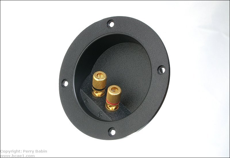
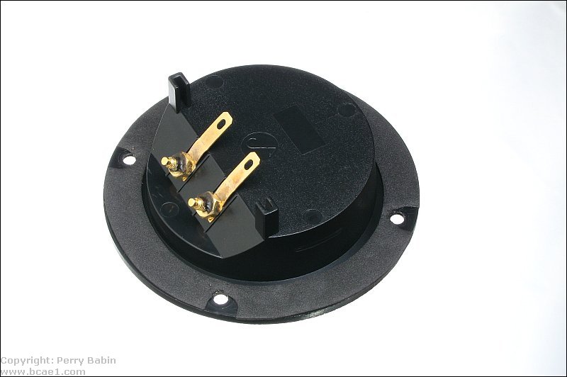
Terminal Cups: Close-up:
 Front and Back:
Sealing Around the Speaker: This is the weather stripping applied around the cutout. I didn't go all of the way around for this example but you DO have to go all of the way around.
 This is a closer view of the same thing.
 This shows the adhesive backing. Some weather stripping has a really thick backing that won't allow you to bend it around the cutout. You need to get something that is similar to what is shown here.

|

|
|

|
 This page will touch on a few new topics (all of which are covered in detail on upcoming pages). It will attempt to help you get what you want from your audio system and your subwoofer in particular.