|
| Email Home Page |
|
|
|
|
| Email Home Page |
|
|
|
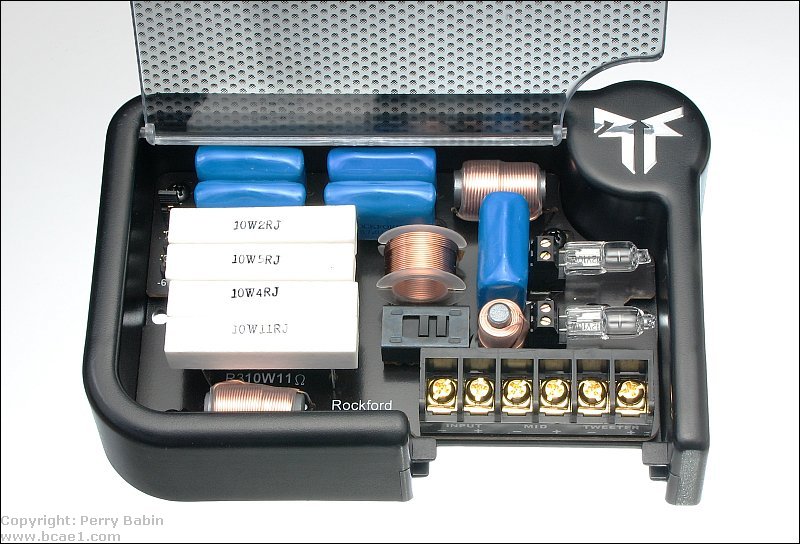
A passive crossover has no active filters as were used in the electronic crossover. It uses coils (inductors) and capacitors to cause a rolloff of the audio level above or below certain frequencies to prevent unwanted portions of the audio from reaching the various speakers. The simplest types use a single coil OR capacitor connected in series with the speaker. If a capacitor is used, the capacitor will tend to block the lower frequencies. If an inductor is used, it will tend to block the higher freqquencies. A capacitor would be used on smaller speakers and tweeters. An inductor would be used on larger speakers (midrange speakers and woofers). When using only an inductor or a capacitor in series with the speaker, the rate of rolloff is 6dB/octave. In a more complex configuration combining both coils and capacitors on each speaker, a steeper rolloff is obtainable. The following crossover is one from a relatively high-end speaker system. It allows you to set the tweeter output to 3 different levels. It allows you to select either 0� or 180� phase for the low frequency speaker and has protection for the tweeters.
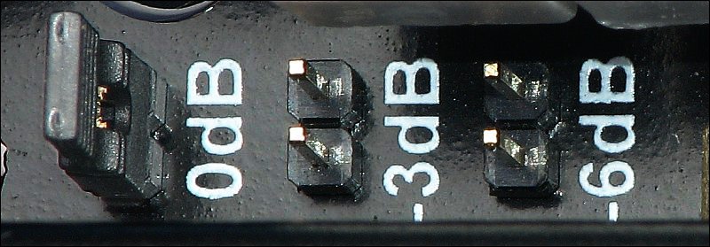
 The next image shows the headers and shunt used to select the various tweeter levels. The shunt (on the 0dB header) shorts the two pins together making the connection between them. When the shunt is moved to the -3dB or -6dB headers, the tweeter output is reduced by the corresponding level (3 or 6 dB). This is used when the owner feels that the tweeters are a bit too loud (too bright).
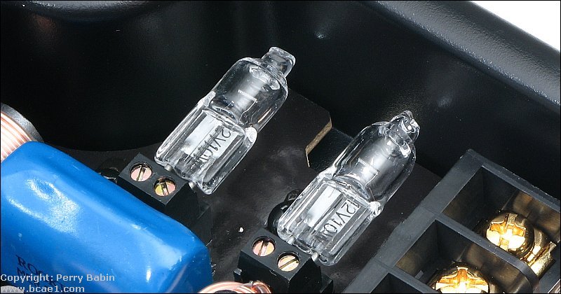
 Some crossovers include components that protect the tweeter. They generally do so by increasing in resistance as more current flows through the tweeter (and the device). When the resistance increases, the current flow is limited and the risk of blowing the tweeters is significantly reduced. In this crossover, 12v lamps are used. If you have a crossover with similar protection, you will see them begin to glow when you drive too much power to the tweeters. Other crossovers use either PTC thermistors or polyswitches.
6dB/octave High Pass Crossover:
----- Critically Important -----
Adobe has deemed that the Flash content on web pages is too risky to be used by the general internet user. For virtually all modern browsers, support for Flash was eliminated on 1-1-2021. This means that those browsers will not display any of the interactive Flash demos/calculators/graphics on this (or any other) site.
The simplest (not the best) fix, for now, is to download the Ruffle extension for your browser. It will render the Flash files where they were previously blocked. In some browsers, you will have to click on the big 'play' button to make the Flash applets/graphics visible. An alternative to Ruffle for viewing Flash content is to use an alternative browser like the older, portable version of Chrome (chromium), an older version of Safari for Windows or one of several other browsers. More information on Flash capable browsers can be found HERE. It's not quite as simple as Ruffle but anyone even moderately familiar with the Windows Control Panel and installation of software can use Flash as it was intended.
6dB/octave Low Pass Crossover:
6dB/octave High and Low Pass Tri-mode Crossover:
Earlier, it was stated that it didn't matter whether the capacitor/inductor was in series with the positive or negative speaker wire. That's true but when using the amp in tri-mode, you have to make sure that the capacitor or inductor is only in series with the speaker that needs it. For example, if the capacitor were installed on the bottom speaker terminal of the amp above and the larger speaker (woofer) were tapped off of the negative terminal of the smaller speaker, the capacitor would be in series with the woofer and the low frequencies would be blocked from reaching the woofer.
Position the mouse cursor over the crossover component values on each side of the graph to see how the slope slides as you change the crossover point. You should also notice how the coils roll off the high frequencies and the capacitors roll off the low frequencies. The straight line is the audio signal level with no crossover components in series with the speakers. The crossover points are roughly based on a 4 ohm speaker. The first time through, you should hold your mouse over each value until the image loads completely.
This demo shows how the crossover point shifts when a 47 microfarad capacitor is used with different speaker loads.
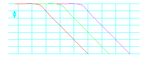
This diagram shows the rolloff characteristics of 3 different passive crossovers each of which consist of a single coil (of different values) creating the rolloff. The vertical lines are one octave apart and horizontal lines are 3dB apart. The red line shows the frequency response of a filter with a 200hz crossover point. The green line has a crossover point of 600 hz. The purple line has a crossover point of 1600hz. The rate of rolloff is only 6dB/octave.
This section shows the math involved in selecting the proper coil for your particular speaker system. This is the formula needed.

Impedance = The rated impedance of the speaker
For this example, let's choose 4 ohms as the speaker's rated impedance. We will use 200hz as the desired crossover point. The output level of a 4 ohm speaker with a 3.18 millihenry coil in series with it, would follow (approximately) the red line. If it were a 4 ohm resistor, instead of a speaker, the frequency response would follow the line exactly. A speaker has inductance in it's voice coil which would make finding the exact response difficult but this equation will get you close to the desired response.
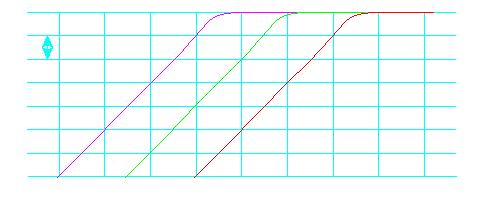
This diagram shows the rolloff characteristics of 3 different passive crossovers each of which consist of a single capacitor (of different values) creating the rolloff. The red line shows the frequency response of a filter with a 3200hz crossover point. The green line has a crossover point of 1200 hz. The purple line has a crossover point of 400hz. The rate of rolloff is only 6dB/octave.
This section shows the math involved in selecting the proper capacitor for your particular speaker system. This is the formula needed.

Impedance = The rated impedance of the speaker
For this example, let's choose 4 ohms as the speaker's rated impedance. We will use 1200hz as the desired crossover point. The output level of a 4 ohm speaker with a 33 microfarad capacitor in series with it, would follow (approximately) the red line. Again, if it were a 4 ohm resistor, instead of a speaker, the frequency response would follow the line exactly. A speaker has inductance in its voice coil which would make finding the exact response difficult but this equation will get you close to the desired response.
This diagram shows 2 different ways to cross subs at 100hz. All of the subs are 4 ohms.
Capacitor Voltage Ratings:
Polarized vs Non polarized Capacitors: For more information on higher order crossovers, go here.
The following demo shows how the crossover's output signal level changes with a change in input frequency or a change in the crossover point. The output sine waves indicate power output. A sine wave half as tall as the original indicates that the speaker would receive only half power at that frequency and crossover point.
Click HERE to open this graphic in a new tab. Right-click to zoom. Left-click to drag.
|
|
You should remember:
1.A passive crossover requires no external power source to operate. 2.A passive crossover uses caps, coils and resistors to reduce the signal level above and/or below a certain frequency. |

|

|
|

|
calculator