|
Etching Circuit Boards
Many DIYers make prototype circuits. These generally begin on a perfboard or a breadboard. The perfboard can produce a reliable device because everything is soldered. A breadboard is for initial prototyping only. Neither of these options results in a good looking project. Having a custom made circuit board is a much better option if the circuit is to be used long term, especially if you take pride in your work. It's possible to get boards produced by board houses but that's usually relatively expensive. $20/board and a minimum of 5 boards is common. Of course, at that price, the boards will be professional quality and will make the project appear to be a commercially produced device. If you want to have boards produced, PCBFabExpress has produced good quality boards for me and they have reasonable prices.
As you already know, most electronic equipment use circuit boards. The circuit board is generally a resin impregnated laminate of some sort. Most of the better equipment use an epoxy fiberglass material. The substrate is copper clad on one or more sides (it can actually be multi-layered - up to about 8 copper layers). Most car audio equipment uses boards that have copper only on top and bottom (although Orion and Zapco sometimes use 3 or 4 layer boards). This allows the board to be smaller (vs a single sided board) because the traces can be on both the top and bottom of the board. If you've never seen a commercially produced circuit board, go to the Printed Circuit Board page.
Prototype Circuit Boards
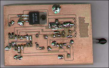
When designing a new circuit or device, after you have a schematic drawn up you build a prototype of it. This allows you to find any mistakes or bugs that you've missed. For simple circuits, you can use a proto board from Radio Shack (as is shown below). This a quick and easy way to make the connections but it also ends up looking like the mess below. Another slightly more time consuming way to make a prototype board is to etch it.
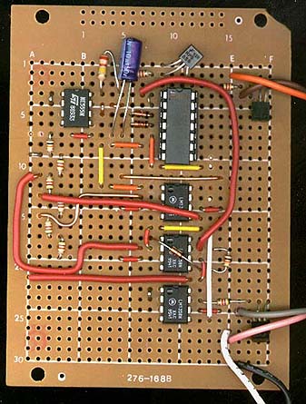
This is the back side of the same proto board before placing the parts. You can see two sets of traces that originate from the top and bottom of the board. They are often used for ground and +B. The other, shorter (3 -hole) traces are tie points.
Layout Editors:
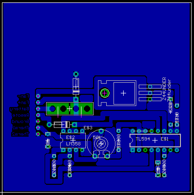
Before etching the board, you need to have a layout pattern. For this, you use a layout editor. A layout editor is a program that allows you to draw out all of the traces and place all of the parts onto the board. It's a lot like a drawing program specifically for circuit boards. Most have 'libraries' that have common parts' layouts (like integrated circuits, resistors, capacitors...). You can use parts from those libraries or make up your own for specialized applications. They also allow you to draw out all of the traces and move things around until you get it exactly as you want it. I personally use 'Eagle' from CadSoft. The freeware version of the software is somewhat limited but it is sufficient for most simple circuits. The image below shows what it looked like in the editor. I was using a 3"x3" board which was more than I needed. That's why there's a lot of blank space at the top. I let the polygon that covers all of the unused areas of the board extend to the full size of the board. This allows the unused copper to be covered by the mask and not dilute the etching solution.
Cleaning the Board:
When you get the circuit board, it will likely be slightly oxidized. This oxidation and any oil from your fingers has to be removed. To do this, I use some 180 grit sandpaper. Sand the board under running water until it's all uniformly shiny. Don't touch the copper after cleaning it. Dry the board with clean paper towels. If you accidently touch the board, clean it with rubbing alcohol.
Toner Method:
There are several ways to get the layout pattern onto the copper clad board. This section will deal with the toner transfer method. The toner in a laser printer or laser copier is a thermoplastic. This means that it melts when a certain temperature is reached. A laser printer or copier uses heat and pressure to transfer the image from a drum or belt onto the paper. For this method, we'll use a regular clothes iron and some elbow grease to transfer the toner from a piece of paper to the copper clad board. In the final board, you'll notice a lot of pinholes in the copper areas. This is due to poor coverage by the toner. This was done with a generic toner cartridge. I've since tried this with a genuine HP toner cartridge and the results were much better.
Using a Good Transfer Medium:
After you've laid out the board in the editor of your choice, you need to print it. If you have a laser printer, you can print the circuit board directly onto the proper paper. If you only have an inkjet printer, you'll have to print it and copy it onto the proper paper using a copy machine (preferably one that has been well maintained). I've tried several different types of paper to transfer the toner. The best was a high gloss photo paper that's designed to work with inkjet printers. The paper has a water soluble coating that's designed to hold the inkjet ink or dye. When used in a laser copier or printer, the toner is printed on 'top' of this layer (it doesn't sink in like inkjet ink does).
Transferring the Image:
Since the board was laid out as a bottom layer in the editor, no reversal of the image was needed (as may be needed if you were laying it out as if you were looking at the bottom of the board). You should cut the layout pattern from the sheet of paper so that it's about 1/16" to 1/8" smaller all around than the actual board. Tape the printed side of the paper to the copper side of the board. Along one side, tape along the full length of the board allowing the tape to contact both the paper and ~1/16" of the circuit board while allowing the rest of the width of the tape to wrap around to the other side of the board. Across from the edge that you just taped down, put another piece of tape perpendicular to the first that you laid down. Lay at least a couple of inches of tape onto the back of the photo paper. You need a lot of contact area because the tape will not stick well to the back of the photo paper. While pulling firmly on the piece of tape, wrap it around to the other side of the board. Now the photo paper should be held firmly down to the copper.
NOTE:
Please check both sides of the photo paper for sensitivity to heat before using it in a laser printer or copier. This can be done with an iron. As I mentioned before, a laser printer (or copier) uses heat to transfer the toner. If the back side of the photo paper melts when heated, it may damage the printer. If you run it through a printer so that it tries to print on the heat sensitive side, it will likely do damage. If it's run through the proper way, it won't likely do any damage. There are photo papers that are not heat sensitive (more likely to be the cheaper stuff). The paper with a backing that melts is more likely to be the stuff with a fancy, smooth backing which is supposed to mimic actual photographic paper.
Now you'll need to get out your iron. I set mine to 'rayon'. Since the back of my photo paper was heat sensitive, I had to put a paper towel between the iron and the paper. Set the iron straight down onto the board/paper. At first, don't move it at all. Let it set there for about 20 seconds keeping moderate pressure on it. Find an edge that's not taped down (preferably not near a fine trace). GENTLY, see if you can pull it up. If you can, you need more heat and pressure. Start moving the iron around putting pressure on the edge of the iron's base (work from the center out). Move around over the entire board for another 30 seconds or so. Give equal time to all of the board. When you have it right, the paper will be absolutely flat on the board and you will not be able to peel it up anywhere. If the board is larger than your iron, repeat the entire heating procedure for each section of the board (again, starting from the center and working your way out). If the toner gets too hot, it may spread out, filling in between traces. If this happens, take a small sharp tool and clean the toner from the areas where it should not be.
Removing the Paper:
Remember that we said that the photo paper has a water soluble coating. We are going to soak the board and paper in hot tap water. Let it set in the water for about 10-15 minutes. When you can start to peel up the edges, hold it under running water that is as hot as you can stand it. GENTLY peel the paper back from the edge. Hold the part, on which you're pulling back, as close to the board as possible. Let the water run on it as you peel it back. It took about 3-4 minutes to do the small (3"x3") board I've shown here. When you get the paper removed, there will be a thin slippery coating on the board. Keep rubbing it with your fingers until it's ALL gone. The toner, when properly applied, is surprisingly tough. It won't generally come off (even if you scratch it with your fingernails). It should look something like the image below. Where ever you can see copper, that's what's going to be removed by the etchant. If there are any scratches in any critical areas, you can touch it up with a permanent marker. Medium and fine tip 'Sharpies'. work well. Sometimes it's better to fill in areas with a series of dots instead of using strokes. It helps deposit more ink onto the board. If you buy the Radio Shack etching kit, it will include a pen. If significant areas of the board layout failed to adhere properly, clean the board again and start over. Use a little more heat and pressure when transferring the toner and allow the board to soak a little longer (overnight if necessary). If you plan on making more boards in the future, try soaking the board in different types of cleaning liquids like Formula 409 or Fantastic. The cleaners will help to break down the coating on the photo paper.
Etchants:
There are 2 popular etchants. Both are effective. Ammonium Persulfate is my favorite. It has a couple of advantages. First, it's clear which allows you to better see what you're doing. It is also less likely to stain everything it comes in contact with. One disadvantage it that it comes in powder form. This means that you have to get the mix right for it to be most efficient. Ferric Chloride is the other etchant. It's a reddish-orange colored liquid. It comes pre-mixed and is more widely available. It's stocked at most Radio Shack stores.
Etching the Board:
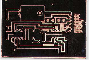
To etch the board, you'll need a shallow glass or plastic container (no metal - the etchant will eat it up and will reduce the effectiveness of the etchant). Having a lid for the container is a bonus. Lay the board in the container with the pattern facing up. Pour the etchant into the container. A larger container will allow more etchant and generally less etching time. If you use too little etchant, it will 'fill up' and stop removing the copper. Every few minutes, tip the container from side to side a few times to keep fresh etchant on the pattern area of the board. If you have a sealed container, it will allow more vigorous agitation and require less etching time. The image below shows the board after the undesired copper has been removed.
Removing the Toner:
Before you can solder the components into the board, you need to remove the toner. This may be done with steel wool or a 'Scotch Brite' type scrubbing pad. When you're finished, you'll have a shiny copper layout. Try not to touch the copper with your fingers because it will cause it to oxidize. Later you'll apply a clear coating to protect it. You'll notice that every little crack or pin hole in the toner mask has resulted in the copper being removed. If one of those cracks were across a trace, it would cause an open circuit and would have to be repaired. After the board is cleaned, look for areas where the copper hasn't been completely removed (between traces, pads or anything else). If there are any short circuits, they must be removed now. If they are not and the device is powered up, there could be significant damage to the board and the electrical components. To cut them free, you can use something like an Exacto knife. Be very careful and take your time.
Detail:
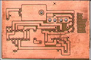
You can see that you can get some fine detail in the circuit board. The image is shown at 3X the original size (it's shown normal size in the other images).
Drilling:
Now the board is ready to drill. For this, you'll need a drill that's capable of holding very fine/small bits. The two most used sizes for me are a #66 and a #60. For number size drill bits, a smaller number is a larger bit. I was too lazy to go find a #66 drill bit so I used a #60 on virtually all of the holes in this board. The drill will have to be small (similar to a Dremel Tool). A Dremel Tool has a fixed chuck and will require special bits. If you're lucky enough to have a small drill with a 3-jaw chuck, you'll be able to use regular bits (which are much cheaper). If you're using fiberglass boards, regular 'high speed steel' bits will wear quickly (after ~50 holes you'll start to notice that they're cutting more slowly). Carbide bits are more durable but break VERY easily. Don't try carbide bits unless you're using a drill press. If you're using non-fiberglass boards (generally made of resin impregnated paper), high speed steel bits will last a relatively long time. When drilling, I usually do so on top of an old phone book. It offers a good sacrificial material that won't dull the bits.
Placing and Soldering Parts:
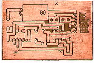
If you haven't read the 'soldering' page yet, do so now. The image below shows the bottom of the board with all of the joints soldered. Since there's no solder mask, you have to be very careful not to bridge between adjacent joints with solder. Cleaning the board with acetone and a tooth brush (out of doors) after soldering will allow you to better see whether or not you have any solder bridges. Compare the board to the printed version of the board layout (or the screen image in the layout editor.
If you look closely, you'll see a small jumper wire connecting two points on the circuit board. I forgot to connect them before I printed it out. Well... it is a prototype. :)
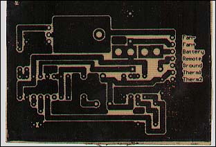
This is the top of the board. The 2 metal clips are a fuse holder for an ATC/ATO fuse. The little black blob is a thermistor. As you can see, it's a very simple circuit with few parts.
If you were curious, this board is a thermally controlled PWM fan driver. It allows the fan to operate more slowly or not at all when the thermistor is cool and will bring the fan to full speed when the thermistor is hot. For car audio, the thermistor would be connected to the heat sink of the amplifier. The hotter the amp got, the faster the fan would run. This was a PWM regulator. While I don't have a schematic for this one, if you want to understand more about linear regulators (could be used as a fan-speed regulator), visit THIS page.
Using Pre-sensitized Boards
Another method of producing prototype boards is to use boards that are coated with a material that's sensitive to UV light. This method is more costly to use because it requires relatively expensive boards and additional chemicals. but can produce very fine boards. Instead of transferring the toner to the board, you print the layout on a transparent sheet. The sheet is laid on top of the board and a piece of glass is laid on top of the pieces to keep the transparency flat on the board. The board is then exposed to UV light which changes the properties of the sensitive material. The board is then bathed in developer and the pattern is left on the board. Be aware that some boards require that you use a 'positive' print and others require a 'negative' print. For one, the area protected by the image on the transparency is left intact. The other removes the area covered by the toner on the transparency.
When using this method, you have to work in a dimly lit room like you would if you were developing film. If the boards are exposed to anything other than very dim light (red light may be acceptable at higher levels), the boards will be ruined.
The rest of the procedure is the same as the same as with the toner method. This simply gets a pattern onto the board so that it can be etched.
|


