|
Modified Punch 45
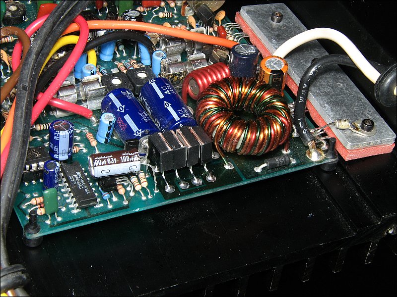
Modifying Punch 45 amplifiers wasn't my idea but I have a couple of friends that like to see how far they can push small amps. Most of the mods were their ideas. I simply offered a few tips to make it a bit more reliable. This is the Rev. F Punch 45 (the one with fuses). It requires very little modification from an electronics standpoint. This particular amp produced ~225 watts RMS into a 1.8 ohm dummy load. It drove a 1 ohm speaker load well but, of course, it ran very hot.
Modifications Performed
-
Output and Power Supply FETs:
Initially, the outputs were rated for only ~12 amps of current. For early mods, IRF3415s were used for the output transistors. For this amp, IRF3205s were used. IRF3205s were used for the power supply in all modded amps.
-
Rectifiers:
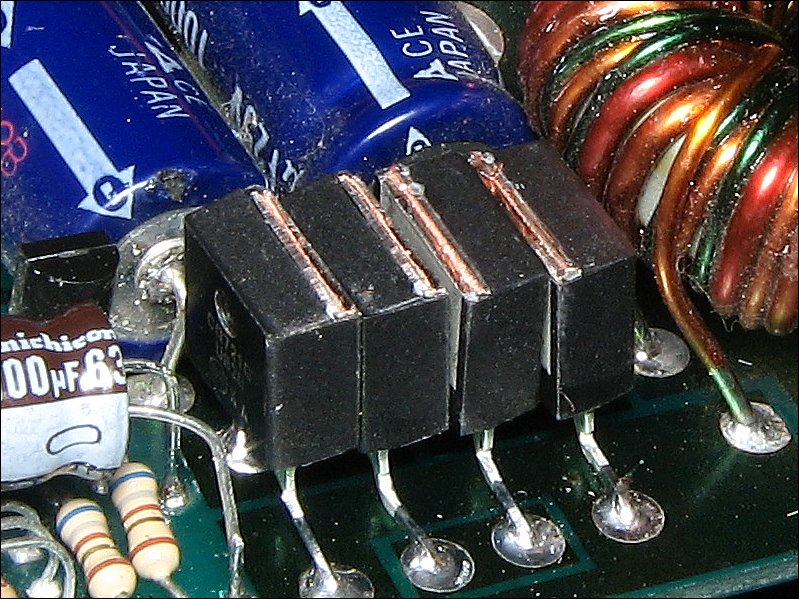
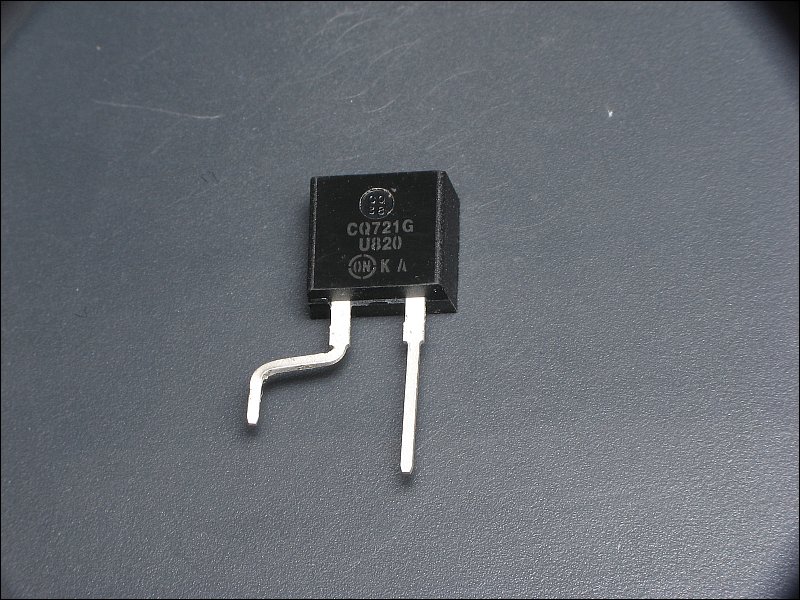
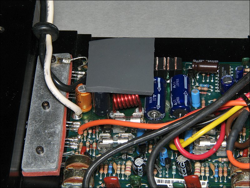
The rectifiers in these amps are a weak point. They commonly run so hot that they cause the solder connections to oxidize. The connections will get so bad that the diodes will no longer have an electrical connection to the circuit board. In this amp, MUR820s were used as replacements. The tabs were cut off so they wouldn't make contact with the bottom cover or the aluminum stock. Notice that they are bent two different ways. The tabs of the center two rectifiers are separated so they can't make contact.
This shows what they look like before they're installed (2 are bent the other way).
In a previous photo, you may have noticed a capacitor (100uF/63v) with its leads bent so that the body of the capacitor is now parallel with the board. The following image shows how the capacitor was installed above other components. It had to be relocated/repositioned to allow the new rectifiers to be installed. If you do this and are concerned about stressing the leads of the capacitor, you can place a drop of adhesive (like GOOP) between the capacitor and the transistor (also bent over). This will take virtually all of the stress off of the leads of the capacitor.
-
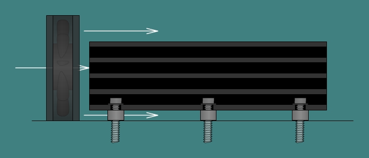
Transformer and Bottom Cover:
When used at low ohm loads (reason for mods), the transformer runs hot enough to cause it to fail. Using a fan to force air into the vents and over the transformer helps. This amp was modified to work without a fan (a fan would still be a good idea if it was going to be driven hard). Two lengths of 1/4" x 3/4" aluminum stock were fastened with screws to the bottom cover. Heatsink compound was applied between the aluminum stock and the bottom cover.
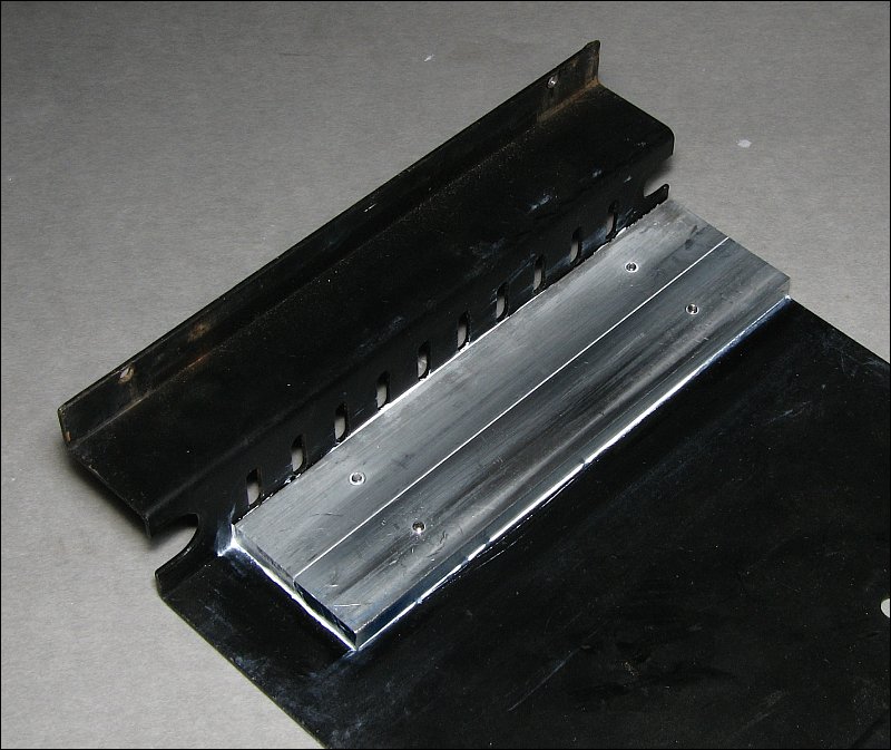
If you do this, you need to make sure that there is proper clearance between the transformer and the stock. You want the transformer to be close to the stock but you don't want it to touch the stock. If there isn't sufficient clearance, it may be necessary to desolder and resolder the transformer so that you have the proper clearance (no less than 1/16" and no more than 1/8" between the transformer and the aluminum stock).
To transfer heat from the transformer to the aluminum stock, silicone gap pad material was used. This material can be found on eBay (search for thermally conductive pad). It's typically used to help cool video cards. If you do this, order the 4mm thick material. It's unlikely that the thinner material will adequately fill the gap.
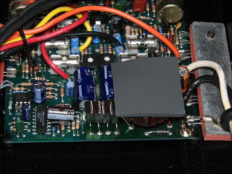
Below, you can see that the gap pad material is on top of the capacitor. This capacitor runs hot and the gap pad help keep it a bit cooler. If the capacitor needs to be replaced, use a 'low impedance' capacitor. Choose a capacitor with the highest voltage rating for the capacitor's value that will fit into the alloted space. Low impedance capacitors typically run cooler than general purpose capacitors. Typically, capacitors with higher voltage ratings (all else being equal) have lower ESR and will run cooler. Also choose a capacitor rated for 105C (rated to operate at 105 Celcius) instead of a capacitor rated to operate only up to 85C. The Panasonic FC series capacitors (available from Digi-Key) are a good choice (until something better comes along).
-
Keeping the Transformer as Cool as Possible:
Since the transformer transfers heat to the bottom cover, the bottom of the amp needs to be raised slightly above the mounting surface. Even 1/2" would be enough to promote better cooling. As was mentioned before, having air flowing over/through the amp will make it run cooler and, in general, a cooler amp will be more reliable. For this amp, placing the fan at the back of the amp (near the transformer) and having it force air through the fins and through the vent holes will provide the best cooling. If it's raised off of the mounting surface, the fan will force air across the bottom cover which will help keep the transformer somewhat cooler. Remember, the transformer is a weak point and needs to be kept as cool as possible if the amp is to be driven hard or is expected to be reliable when used daily at low ohm loads.
-
Fuses:
The original fuses were 5 amp fuses. Those wouldn't hold up for long driving low impedance loads. 7.5 amp fuses were used in this amp and held up well to the 1 ohm load.
Well... That's about it. Several amps have been modified like this (all with slight variations) and they've held up well. They will drive some 1 ohm loads (speakers and enclosures cause various combinations to be tougher to drive than others) without a problem. As was mentioned earlier, using a fan is a good idea when doing this. Feel free to email me if you have any questions.
|


