All amplifiers designed for 12 volt car audio applications that are capable of producing more than 25 watts into a 4 ohm load employ some sort of switch mode power supply. The most practical way to boost voltage is through the use of a transformer but a transformer must be driven with an A.C. voltage or a switched D.C. voltage. The charging system in an automobile produces D.C. Now I know there will be more than a few smart @$$es which will say an alternator produces A.C. and they are correct but (in virtually every case) the A.C. is rectified to D.C. before it leaves the alternator. To simulate the A.C. needed to drive the transformer, the D.C. on the primary of the transformer is switched on and off at a very high rate of speed. Most designs use a center tapped primary which means the transformer is driven in push-pull configuration. As far as the transformer is concerned, the switched D.C. appears to be A.C. The next few paragraphs will explain the specific ways which manufacturers actually drive their power supplies.
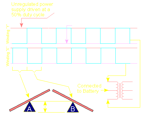
The cyan colored line (above) is a graphical representation of the voltage present on each of the primary windings (and is similar to what you'd see if you were looking at the waveform on an oscilloscope). You can see that when one of the windings (x or y) is pulled to ground, the second winding (which is magnetically coupled to the first winding) is forced up to twice the battery voltage. When the cyan line is low, that winding is being driven to ground (someone pushed one end of the see-saw down to the ground). When the line is high, the opposite winding is being driven to ground. As you can see, there is no point in time where both windings are being driven to ground. If, for some reason, they were both driven to ground (at the same time), the transistors driving the windings to ground, would likely be damaged (probably even before the fuse could blow). The 'A' see-saw shows the voltages for the first half of the cycle and is indicated by the first yellow bracket. The voltages on the windings for the second half of the cycle is shown by see-saw 'B'.
Note: 50% duty cycle refers to 1/2 of the primary. Since both halves of the primary are being driven (each ~50%), the transformer is being driven 100% of the time. .
Winding Ratio:
As we said on an earlier page, the ratio of primary windings to secondary windings determines the ratio of primary voltage to secondary voltage. When the primary windings are driven in the push-pull configuration, the effective primary A.C. voltage is twice the battery voltage. For a 12 volt system, the primary would see 24 volts of pulsed D.C. Imagine a 'see-saw'. If it is well balanced with no external forces applied, it will be level. If you sit on one side, the other end will go twice as high as it was at rest (with the ground as a reference). The same would happen if you would go sit on the other side. If you could switch from one side to the other at 25 thousand times per second, you would be simulating the voltage present in a switch mode power supply (and working up a good sweat).
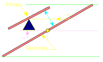
If the ratio is 1:2 (primary:secondary) and the primary voltage is 24 volts (double the 12 volt battery voltage), the secondary voltage will be 48 volts. The secondary voltage is directly proportional to primary voltage. The following diagram shows (with the lame see-saw analogy) how the secondary winding generates a voltage proportional to the primary winding and the transformer ratio. You can see the primary 'pivots' on the 12 volt fulcrum (remember that we're talking about a center tapped primary which is connected to a 12 volt power source). This means that the ends of the see-saw will go from 0 volts (ground) to twice 12 volts (24 volts). The secondary (larger see-saw) pivots on ground because it's center tap is connected to ground. The primary and secondary are magnetically coupled by the transformer core (cyan line). You can see that the total voltage swing of the secondary (shown by white line) is twice the swing of the primary voltage. With a 1:2 ratio, this will cause the secondary to swing a total of 48 volts. Since the secondary is center tapped at ground, it actually swings 24 volts above ground and 24 volts below ground. This transformer would be used in an amplifier with rail voltage of �24 volts. After the secondary AC voltage was rectified and filtered, this would allow (ignoring losses) the audio to swing to approximately �24 volts.
In the following flash demo, you can see the see-saw thingy again. If you press the 2nd button it shows the ratio of 5:8 (primary to secondary). If you press the 3rd button, the transformer is driven. To slow things down, this shows how the primary and secondary would be driven with a sine wave. A square wave would 'snap' the voltage to either the maximum OR the minimum voltage (not smoothly like it shows here). When the transformer is being driven, you can see the magnetic field that couples the primary winding to the secondary winding. Remember that there is no direct electrical connection between the windings. All of the energy is transmitted through the magnetic field. If this were driven by the mains in the US, it would be driven about 300 times faster than shown here.
In this demo, you can see that I added the FETs and replaced the wood planks with coils of copper wire (no, really, that's what they're supposed to be). You can see that when the FET is ON, it pulls one winding of the transformer (see-saw) down. When the other FET is on, the other winding is pulled down. As you can see when the supply is not switching (off), the voltage on both ends and the center tap of the primary is at 12 volts (the battery voltage). Since the secondary center tap is connected to ground, the voltage on all of the terminals (center tap and the opposite ends of the windings) is at 0 volts. The voltage will only be higher (or lower) than ground when the primary is driven and the magnetic field induces voltage in the secondary. In a real circuit, it would operate about 25,000 times faster.
This site was started for pages/information that didn't fit well on my other sites. It includes topics from backing up computer files to small engine repair to 3D graphics software to basic information on diabetes.
This site introduces you to macro photography. Macro photography is nothing more than the photography of small objects. It can take quite a while to understand the limitations associated with this type of photography. Without help, people will struggle to get good images. Understanding what's possible and what's not possible makes the task much easier. If you need to photograph relatively small objects (6" in height/width down to a few thousandths of an inch), this site will help.
If you're interested in air rifles, this site will introduce you to the types of rifles available and many of the things you'll need to know to shoot accurately. It also touches on field target competition. There are links to some of the better sites and forums as well as a collection of interactive demos.
This site helps anyone new to computers and anyone with a basic understanding of computers with a desire to learn more about the internal components of a computer. If you have a computer that you'd like to upgrade but don't know where to start, this is a good site for you.
This site is for those who want to begin racing karts but don't fully understand how the various parts work. It's mostly interactive demos that show how the various parts of the kart work.
OK, enough of the refresher course
Click here to close this window.