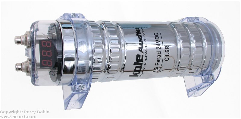
Many car audio enthusiasts only know capacitors as the devices shown below and to the right. While capacitors are absolutely required by electronic devices (amplifiers, head units, MP3 players...), it's not always a good thing to have more than you need. In my opinion, these capacitors, connected outside of the amplifiers, serve virtually no purpose and rarely solve any problems. In almost every instance where something improved when the capacitor was installed, an unknown problem was repaired (corroded wire, loose connection...). This doesn't apply to this brand of capacitor alone. This applies to virtually all of the 'farad' capacitors. This page will not only cover the large capacitors like these but smaller capacitors as well.
As a side note...
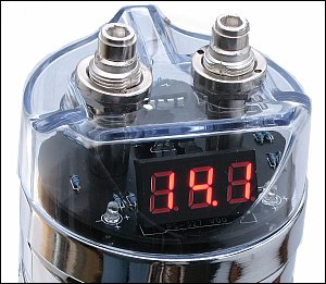
I tested this capacitor with an LC102 capacitor analyzer and it failed every test. I removed the display board to confirm that the board was not causing it to fail the tests. It still failed. The capacitance was less than 0.350F. Large electrolytics generally have a tolerance of +10%/-20% but this was well outside of that. To confirm that the analyzer wasn't defective, I tested an old Rockford 1/2F cap and it read very near it's rating. This could be a one-in-a-million failure but I doubt it. Most consumers don't have professional test equipment to check their capacitors.
What is a Capacitor?
A capacitor is an electronic device which consists of two plates (electrically conductive material) separated by an insulator. The capacitor's value (its 'capacitance') is largely determined by the total surface area of the plates and the distance between the plates (determined by the insulator's thickness). A Farad is the unit used to express a capacitors ability to store energy. For most circuits, nothing approaching one Farad is needed. Very often, smaller capacitors like a 0.1uF capacitor will be enough. Capacitance is offten expressed in microfarads. One microfarad is 1/millionths of a Farad. The 0.1uf that was mentioned is 1/10th of a microfarad.
Schematic Symbols for Capacitors
The following schematic symbols are some of the symbols used in schematic diagrams. The ones with a '+' sign are for polarized capacitors (capacitors that must be connected properly with respect to the positive and negative power supply terminals). Non-polarized capacitors are typically used for circuits with AC voltage (which includes audio circuits).
Capacity/Capacitance:
This analogy should help you better understand capacity. In the following diagram, you can see 2 tanks (capacitors) of different diameter (different capacitance). You should readily understand that the larger tank can hold more water (if they're fill to the same level (voltage)). The larger capacitor has more area in which to store water. Just as the larger capacitor's larger plate area would be able to hold more electrons.
----- Critically Important -----
Flash graphics viewing/use alternatives:
Flash support by most modern browsers has been dropped but that's not the end of the line for Flash.
There is no practical alternative to Flash for the interactive demos/applets/graphics on this site.. Especially when there are alternatives, some simple, some good, some...
Ruffle is chosen by most because they can't imagine using anything but their preferred browser. It works. It's OK but not great. The Flash graphics won't look as they're supposed to but it, generally, works.
The #1 preferred (by me) way to view the site and the Flash graphics is with the Chromium Portable browser and the installation of the older (no time-out) Flash Player files. This was incredibly simple when people knew computers but not today when people only know how to work with their phones.
The Flash Browser is a good option but it's so stripped down that it makes it somewhat difficult to use.
The Maxthon browsers are an option. The v4.95 is the easiest (install and use). V5.3.8 and 6.1.0 require (very) slightly more effort (very).
The Chromium and Maxthon browsers on the page above are 'portable' browsers. They are not installed into your system. They are simply made available for use on your computer. They can be carried around on a Flash drive and used on any computer.
----- Critically Important -----
Capacitor and DC Voltage:
When a DC voltage source is applied to a capacitor there is an initial surge of current, when the voltage across the terminals of the capacitor is equal to the applied voltage, the current flow stops. When the current stops flowing from the power supply to the capacitor, the capacitor is 'charged'. If the DC source is removed from the capacitor, the capacitor will retain a voltage across its terminals (it will remain charged). The capacitor can be discharged by touching the capacitor's external leads together. When using very large capacitors (1/2 farad or more) in your car, the capacitor partially discharges into the amplifier's power supply when the voltage from the alternator or battery starts to fall. Keep in mind that the discharge is only for a fraction of a second and typically is not really beneficial. The capacitor cannot act like a battery. It only serves to fill in what would otherwise be very small dips in the supply voltage. The problem is.. after they partially discharge, they're going to have to recharge. When the voltage begins to rise, they are drawing current that could be going to your amplifier.
Capacitors and AC Voltage:
Generally, if an AC voltage source is connected to a capacitor, the current will flow through the capacitor until the source is removed. There are exceptions to this situation and the A.C. current flow through any capacitor is dependent on the frequency of the applied A.C. signal and the value of the capacitor. I will go into more detail
on a later page.
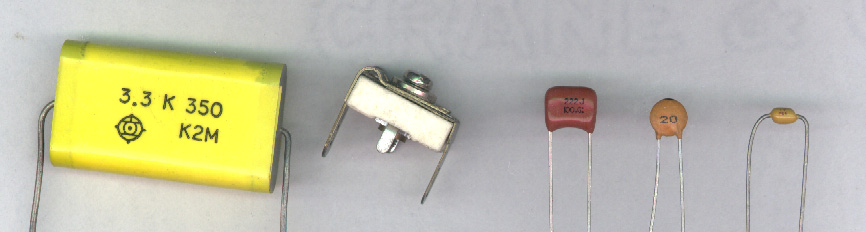
Capacitors from left to right: 3.3 microfarad polypropylene, adjustable trimmer cap, .0022 microfarad polyester, 20 picofarad ceramic radial capacitor, 15 picofarad ceramic axial capacitor.
ESR:
ESR is the equivalent series resistance of a capacitor. An ideal capacitor would have only capacitance. As you remember, all conductors have resistance. In a capacitor, there are multiple conductors like the wire leads, the foil and the electrolyte. The resistance of all of the conductors contribute to the capacitor's series resistance. It's essentially the same as having a resistor in series with an ideal capacitor. Capacitors with relatively high ESR will have less ability to pass current from its plates to the external circuit (to the amplifiers in the case of large 1F+ capacitors in car audio). Low ESR is desirable when using a capacitor as a filter.
ESL:
ESL is the equivalent series inductance of a capacitor. Since most electrolytic capacitors are basically a large coil of flat wire, it will have even more inductance than it would have if it were flat. This inductance, along with the small amount of inductance from the wire leads, will make up the ESL of the capacitor. The ESL is essentially the same as having an inductor in series with an ideal capacitor. Low ESL is desirable when using capacitors for filtering purposes.
Leakage:
Even though a capacitor's plates are insulated from each other, there is a small amount of 'leakage' current between its plates. This current is generally insignificant but will cause a capacitor to slowly discharge with no external circuit path between the capacitor's leads.
Note:
Some large capacitors used in car audio systems have a digital voltmeter on them. Some of these displays will have a remote turn on lead to turn on the LED display. Others will have a timer that will turn the display off after a few minutes. If, in either case, the capacitor's positive lead was removed from the power source (and the display remained on), the capacitor would be quickly discharged by the display. This is not the same as the leakage current that we previously discussed.
Film Capacitors:
Many low value capacitors (less than 1 microfarad) will have a plastic type of insulator (polyethylene, polypropylene...) between the plates. Sometimes the plates are actually a metallized layer bonded onto one side of the plastic material. Multiple layers of the metalized plastic material make up the capacitor. Adding layers or increasing the size of the layers (without increasing the thickness of the layers) will increase capacitance. The following diagram is an incredibly generic film capacitor. You can see the dark blue insulating film between the cyan and violet plates. The plates are soldered to one of the terminals on one end of the plates. Half of the plates are soldered to terminal A and the other half of the plates are soldered to terminal B.
Electrolytic Capacitors:
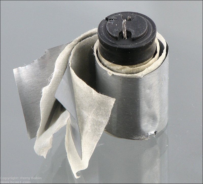
Electrolytic caps are more complex than film capacitors and are generally used for larger capacitance values (0.47 microfarad and higher). The electrolytic capacitor generally consists of 2 layers of aluminum foil with a layer of paper material between the plates (see below). The aluminum plates are anodized on one side to prevent them from passing DC current. The paper would ordinarily act as an insulator but it's saturated with an electrolyte solution which makes it conductive.
Electrolytic Capacitor Foil:
The aluminum foil that makes up the plates in the electrolytic capacitor is treated in a few different processes to make it work properly and more efficiently. The most important process is the anodizing of the foil. Anodizing is a process that forms a very thin layer of aluminum oxide on one or both sides of the foil when the foil is immersed in an acidic solution and direct current is applied to the foil (one lead of the DC power supply is connected to the foil and the other is connected to a conductive plate in the acidic solution). This layer of aluminum oxide is the dielectric (insulator) and serves to block the flow of direct current. To increase the surface area on the foil (and ultimately increase capacitance), the foil can be etched by a chemical process. This would be done before the anodizing.
Paper Element and Electrolyte:
The paper element serves to hold the electrolyte in place. The electrolytic solution (generally ethylene glycol and ammonium-borate) can vary in content but must generally serve a couple of purposes. First and foremost, it must be electrically conductive to help pass the electrons from one plate to the other (the glycol part of the solution does this). Secondly it helps to heal any areas of the dielectric that become damaged (the ammonium-borate does this). If the conductive properties of the electrolyte were absent, the capacitor's value would be drastically reduced. If the healing properties were absent and the anodized coating was scratched or otherwise damaged, the capacitor would leak DC from plate to plate. The healing properties greatly increases the useful life of the capacitor.
Reverse Voltage:
Electrolytic capacitors generally have a positive and a negative terminal. As we said earlier, the plates (foil) of the capacitor are anodized with a DC current. This anodizing process sets up the polarity of the plate material (it deteremines which side of the plate is positive and which is negative). We also said that part of the electrolyte was to help heal a damaged plate. Since it has the properties to heal a damaged plate, it has the ability to reanodize the plate. Since anodizing process can be reversed, the electrolyte has the ability to remove the oxide coating from the foil. This would happen if the capacitor was connected with reverse polarity. Since the electrolyte can conduct electricity, if the aluminum oxide layer is removed, the capacitor would readily pass direct current from one plate to the other (it would basically be a short circuit from one plate to the other). This would, of course, render the cap useless.
Over Voltage:
All capacitors have a voltage rating. This tells you how much voltage the dielectric (insulator) can withstand before allowing DC to pass between its plates. Sometimes a capacitor has a working voltage (i.e. WVDC working voltage DC) and a surge voltage. The working voltage tells you how much voltage the capacitor can withstand long term (for the normal life of the capacitor). The surge voltage is the voltage is can withstand for short periods of time. Generally, if too much voltage is applied to a capacitor, it will fail. In electrolytic capacitors, the forming voltage (voltage used to anodize the plates) and the thickness of the paper element determine the working voltage of the cap. In film type capacitors, the insulating material (polyethylene, polypropylene...) will determine the maximum working voltage.
16 Volt Capacitors vs. 20 Volt Capacitors:
As you've likely noticed, large 1 farad (and 1/2 farad) capacitors are available in both 16v and 20v versions. As was said above, the voltage rating tells you how much voltage the capacitor can withstand. It does NOT tell you how much voltage it will have when connected to your system. If both a 16v and a 20v capacitor are conected to the electrical system (with a voltage of 14.4 volts), both the 16v capacitor AND the 20v capacitor will have exactly 14.4 volts. The voltage on the capacitor will be the same as the circuit to which it's connected. In this situation, both the 16v and the 20v capacitors (which have identical capacitance ratings) will hold precisely the same amount of energy. If (IF) the capacitors were charged to their maximum working voltage, the 20v capacitor would hold more energy because it can survive higher voltage. As you can see in the diagram below, all of the electrical components have the same level of water in them (they have the same voltage). If you continue this analogy, you'll be able to imagine that the lower voltage capacitor would 'overflow' if the voltage would go too high (above 16 volts). The 20 volt capacitor could accept a higher water level (voltage) before it overflows. You can also see that when the capacitors are fully filled, the 20 volt capacitor can hold more water (energy). But... in this situation (and in a car), they hold the same amount of energy.
As a side note... The volume of water that a cylinder can hold is equal to the surface area of the cross section of the cylinder (which is analogous to the surface area of the capacitor's plates) multiplied by the height of the cylinder (which is analogous to the voltage that the capacitor's dielectric (insulator) can withstand). Increasing the surface area and/or height of the cylinder (the maximum voltage rating) will increase the maximum volume (charge) the cylinder can hold.
Voltage Rating vs ESR:
For other types of capacitors (like the ones used on the circuit board in your amplifier), sometimes capacitors with a voltage rating higher than the operating voltage is beneficial. Capacitor rated for higher voltage will have to have a thicker dielectric (insulator) between the plates so that the higher voltage can't punch through the insulator. To get the capacitance back up, they have to use larger plates. The larger plate area can reduce the internal resistance and make the capacitor operate at lower temperatures when the capacitor is stressed (when too much current is passed through the plates). This could apply to the large 1F type caps but they're often so poorly constructed that they really don't function as you would expect them to do.
Overheating and Venting:
An electrolytic capacitor will generally overheat if subjected to adverse conditions such as overvoltage or reverse polarity. This will cause the electrolyte to boil off which will create pressure in the sealed aluminum can that envelopes its internal components. If there were no form of controlled venting, the capacitor would eventually explode. For safety's sake, capacitor manufacturers employ some sort of pressure relief that will fracture before the capacitor's aluminum enclosure. On smaller capacitors, the vent are simply a few stamped lines in the top of the capacitor. The stamping weakens the aluminum casing slightly and allows venting when the capacitor's internal pressure reaches dangerous levels. The other type of vent (used on very large capacitors) is a plug that will blow when pressure reaches dangerous levels.
Large Capacitors (1 Farad+):
Large capacitors are connected to the amplifier much the same way a battery is. This means that the capacitor's positive terminal is connected to the amplifier's positive terminal (which also means that it's connected to the battery's positive terminal). The same is true of the capacitor's negative terminal (the cap's negative terminal is connected to chassis ground with the amplifier's negative ground terminal). Like this...
Large capacitors are used as a sort of electrical shock absorber. As voltage starts to rise, the capacitor will absorb energy which will tend to keep the voltage from rising as quickly as it otherwise would. If the voltage starts to fall, the capacitor's stored energy will flow out of the capacitor to try to keep the voltage up. A capacitor's ability to absorb/release energy from/to external circuits depends on the capacitor's specs (capacitance, ESR, ESL...), the output impedance of the power source (alternator and power wire in this case) and the circuit's input impedance (into the amplifier's power supply).
Power Source with NO Capacitor:
In the following diagram, you can see that the output voltage (red jagged line) of the power supply is not very steady (with respect to the white reference line). This variation may be due to some defect in the power supply or from varying current draw from other devices that might be connected to the power supply. You can see that the capacitor is NOT connected to the power supply.
Power Source with Capacitor:
In the next diagram, you can see that the capacitor is connected to the power supply and the voltage is much more stable (smaller ripples). The actual amount of smoothing would depend on a lot of things like the source's output impedance, the resistance in the wire and the current draw from other devices.
Power Source with Series Resistance:
The following diagram shows how series resistance (not ESR) allows the capacitor to smooth the voltage even more. The series resistance will allow the cap to smooth the voltage but would cause a voltage drop if current is drawn from the capacitor. Some low current power supplies may be designed in this way to provide a very smooth output voltage. This will generally only work well if the current draw is constant and known when designing the power supply.
Large Caps and Car Amplifiers:
The following diagram shows how the voltage could drop if the alternator's regulator couldn't react quickly enough to prevent a voltage drop. You should notice that the capacitor is not connected. The white line is the alternator's regulated voltage (approximately 13.8 volts). The dips are where the current draw is high. The deeper dips are points where the current draw is even higher.
The diagram below shows what a large capacitor is supposed_to_do for a car audio system. You can see how the ripple is reduced now that the capacitor is connected. The dips in voltage are smaller. If the capacitor does its job, the added voltage (less voltage drop means higher voltage available to the amplifier) would give you more power output, especially with amps with unregulated power supplies. You probably noticed that I said 'supposed_to_do' earlier. This is because there has been some discussion as to whether a capacitor is a help or a hinderence when it comes to keeping the voltage at a higher level than without it. Of course, if you ask someone that's spent more than $100 on a capacitor if it helped, they'll tell you that it has. Why on earth would someone 'fess up' to wasting that much money on 'snake oil'. I've yet to see a capacitor make an audible difference.
NOTE:
For maximum benefit, you should keep the length of wire between the capacitor and the amplifier to a minimum. Anything (wire, distribution blocks, fuses...) between the capacitor and the amplifier will reduce the capacitor's ability to quickly supply the current needed by the amplifier. Of course, if you have multiple amplifiers and want the capacitor to benefit all of them, you'll have to connect it to the distribution block.
Charging large capacitors:
When connecting a large capacitor (1/2 farad or larger) to the 12 volt source, you may want to charge it slowly before making the final connection to the power wire. Most capacitors come with a resistor to charge the cap slowly. If you're working on your system, and disconnect the capacitor, the cap may get discharged (something might accidentally touch across the terminals or it may partially self discharge over time). If you can't find the original resistor to recharge the cap, you can recharge it with a standard test light (you know, the one with a light bulb, not one of those fancy pants test lights with LED indicators). There's a somewhat helpful demo near the bottom of the page.
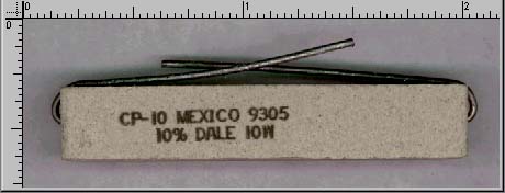
If you don't have a test light and want to use a resistor to charge or discharge your capacitor, use a ceramic encapsulated high power resistor like the one below (I'd recommend using a resistor rated for 10 watts or more and about 20 ohms). If you use a small resistor (i.e. a 1/4 or 1/2 watt) of too low value (less than 100 ohms), it may get hot enough to seriously burn your fingers.
Ruler values are in inches.
The reason you may want to charge a cap slowly is to reduce the arcing involved with fast charging. This arcing won't hurt the cap but it might damage the chrome or gold finish on the connectors.
This demo shows how the test light brightness indicates the charge level in the capacitor. Put your cursor over each capacitor charge status and watch the brightness of the test light. If you have a slow connection, it may take a second or two for each image to load. Click on the amplifier below and the image's position will be optimized.
Discharging the Capacitor:
If you're going to remove your capacitor for some reason, you may want to completely discharge the capacitor to prevent creating a hazardous situation. To discharge the capacitor (after it's disconnected from the system), simply provide a path for the current to flow from one terminal to the other. You can use either the test light or the resistor. After it is discharged, you may want to connect the terminals together with a piece of wire or resistor. Some large capacitors will act like a battery and develop some small voltage across its terminals. Since the capacitor is likely a large capacitor (over 1/2 farad), the small voltage could be dangerous. Even if your capacitor's design doesn't cause it to develop a significant voltage when not in use, leaving the terminals connected will leave no doubt whether the cap is charged or not.
Charging with a Resistor:
If you need to know how long it will take to charge a capacitor with a given resistor, you can use the following calculator. The output data tells you how long 'one time constant' is (time to reach 63.2% of the difference in voltage between the capacitor's voltage and the supply voltage). It also tells you how much time it will take the capacitor to become charged. Lastly, it tells you the maximum power dissipation across the resistor (use this value as a guide in selecting a resistor).
Time Constant:
A capacitor's time constant is the time it takes for the capacitor to charge to 63.2% of the supply voltage when charged through a given resistor. At the end of one time constant, if the supply voltage is 10 volts, the capacitor will have charged to 6.32 volts. A capacitor is condidered to be fully charged after 5 time constants. After 5 time constants, the capacitor will have charged to 99.2% of the supply voltage. The following chart shows the charging curve for a 1 farad capacitor and a 50 ohm resistor. As you can see, the capacitor charges more quickly at first and then (as the difference between the capacitor's voltage and the supply's voltage is reduced) the rate of charge slows. As the capacitor reaches full charge, the current flow is reduced to nothing.
Time Constant Calculations:
The formula for 1 time constant is T=RC where T=time in seconds, R=resistance in ohms and C=capacitance in farads.
For a 1 farad capacitor and a 50 ohm resistor...
T=RC
T=50*1
T=50 seconds
This means that the voltage across the capacitor will be at 63% of supply voltage (8.72 volts for a 13.8 volt supply) after 50 seconds. Earlier, I said that the time constant is the time to charge 63.2% of the difference in voltage between the capacitor's voltage and the supply voltage. After one time constant the voltage across the cap was 63% of the supply voltage. This means that the voltage across the charging resistor is now only 37% of the supply voltage (instead of 100% of the supply voltage when the capacitor was fully discharged). This will reduce the current flow through the resistor into and into the capacitor. For the second time constant, the capacitor's voltage will increase only 63% of the voltage across the resistor. (13.8-8.72=5.08 volts).
For the second time constant...
13.8-8.72 = 5.08 volts (voltage across resistor at beginning of second time constant)
5.08*.632 = 3.21 volts (63% of the voltage across the resistor)
At the end of the second time constant, the voltage is going to be the voltage at the end of the first TC plus the voltage increase from the second TC. In this case, it was 8.72 volts + 3.21 volts or 11.93 volts. If you look at the chart above you can see that the charging curve crosses the 11.93 volt mark at 100 seconds (2 time constants).
Calculating Voltage at any Given Time:
If you want to know the voltage at any given point in time, we can use the following formula. We'll use 65 seconds in this example.


 Many car audio enthusiasts only know capacitors as the devices shown below and to the right. While capacitors are absolutely required by electronic devices (amplifiers, head units, MP3 players...), it's not always a good thing to have more than you need. In my opinion, these capacitors, connected outside of the amplifiers, serve virtually no purpose and rarely solve any problems. In almost every instance where something improved when the capacitor was installed, an unknown problem was repaired (corroded wire, loose connection...). This doesn't apply to this brand of capacitor alone. This applies to virtually all of the 'farad' capacitors. This page will not only cover the large capacitors like these but smaller capacitors as well.