|
More on CPUs
|
|
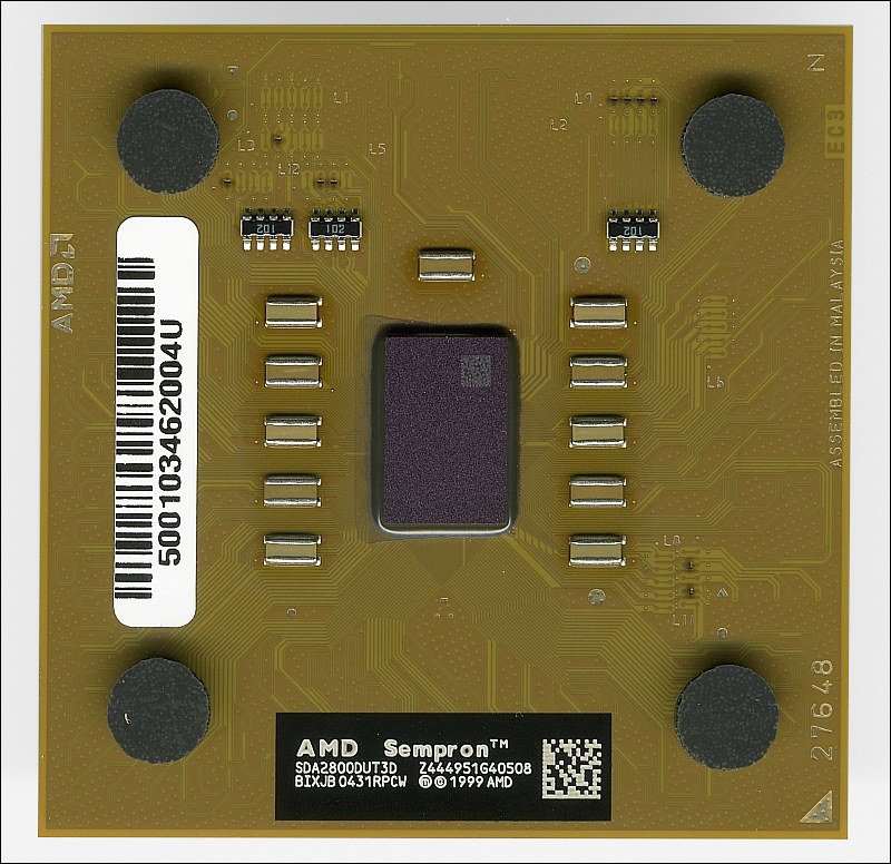
Earlier, we discussed CPU (processor) basics. Here we will go into more detail. In the image below, you can see a view of the top of a processor. This particular processor is an AMD Sempron 2800+. Of the entire piece below, the 'actual' processor is only the little gray piece in the center. Since there are so many electrical connections on the tiny processor, it has to be mounted into the larger assembly. If it were not, the interface connections/contacts would have to be approximately the size of a human hair and would not be reliable in the real world.
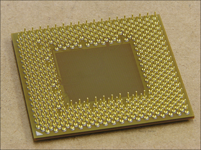
 In the following image, you see the bottom of the same processor. This processor fits 'socket A' motherboards. It has 462 pins. This is a relatively low pin count and will likely soon be phased out.
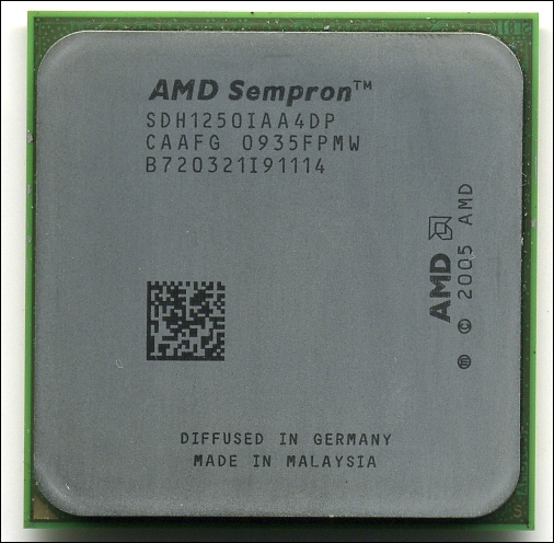
 The following image shows a newer Sempron processor. On the newer processors, the processor has a heat spreader to more efficiently transfer the heat to the heatsink. The processor is still a fraction of the size of the processor module. This processor module has 940 pins (socket designated as AM2). The extra pins are used for better (faster) communications between the processor and the memory as well as other peripheral ICs on the motherboard.
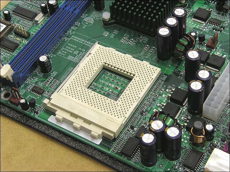
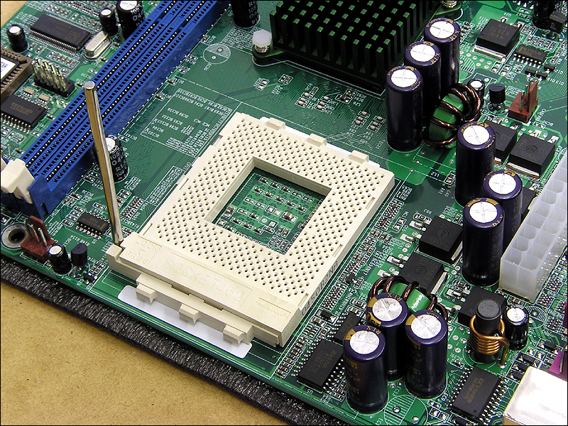
Below, you see a 'socket A' motherboard. If you look closely in the following images, you can see that it says 'socket 462'. That's used interchangeably with 'socket A'. Along the far side of the socket, you can see a long metallic handle. That handle is used to lock/unlock the socket. As you can see, the CPU has a lot of pins. To keep a good contact on the pins, there has to be a fair amount of clamping pressure on each of the pins. When you clamp down on any pin in any socket, it takes a fair bit of force to pull the pin from the socket. Even if it only takes a single ounce of force for each pin, the force to remove the CPU would be nearly 30 pounds. Simply pulling the CPU from a standard type socket, would destroy it. To get good contact pressure AND allow acceptable removal/insertion force, the socket has a slide mechanism that disengages the contacts. This type of socket is called a Zero Insertion Force (ZIF) socket. When the handle is down, the pins are clamped. When the handle is up, the pins are released.
 This next image shows the handle in the 'free' position. When the handle is in this position, inserting the CPU should take virtually no force. Ideally, gravity should provide enough force to fully seat it. Typically, it takes a very slight force (only a few ounces of force) to seat it. If it takes any more than that, pull the processor and check for bent pins. A bent pin on a processor is a very bad thing. Often, they're made of a relatively brittle material and if badly bent will break when straightened. If a pin gets bent, very slowly straighten it. If it breaks, there is little chance that the processor will work. Also, the manufacturer will not warranty a processor with broken pins. For that reason, you must be very careful when handling the processor. It should either be in the original shipping container or in the socket.
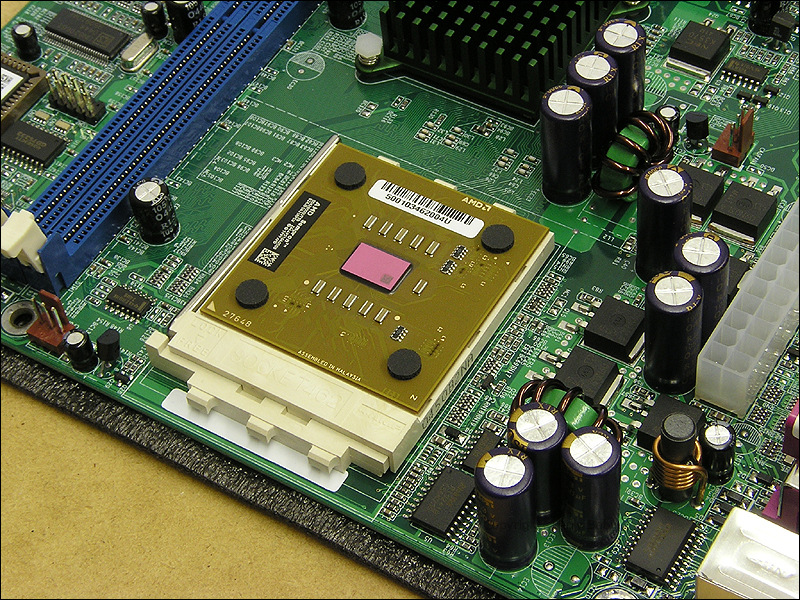
 Here, you can see the processor in the unlocked socket. If you notice, there is a triangle in the corner of the CPU. This helps you to get it properly oriented in the socket. In the previous images, you can see that the socket has missing holes on the corners along one edge and the CPU has corresponding missing pins.
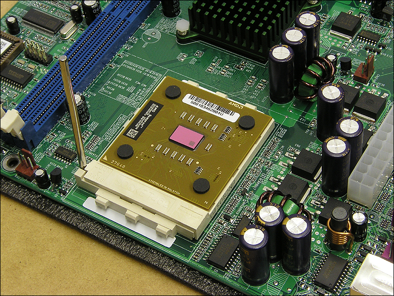 Here (below), we see the processor locked down into the socket.
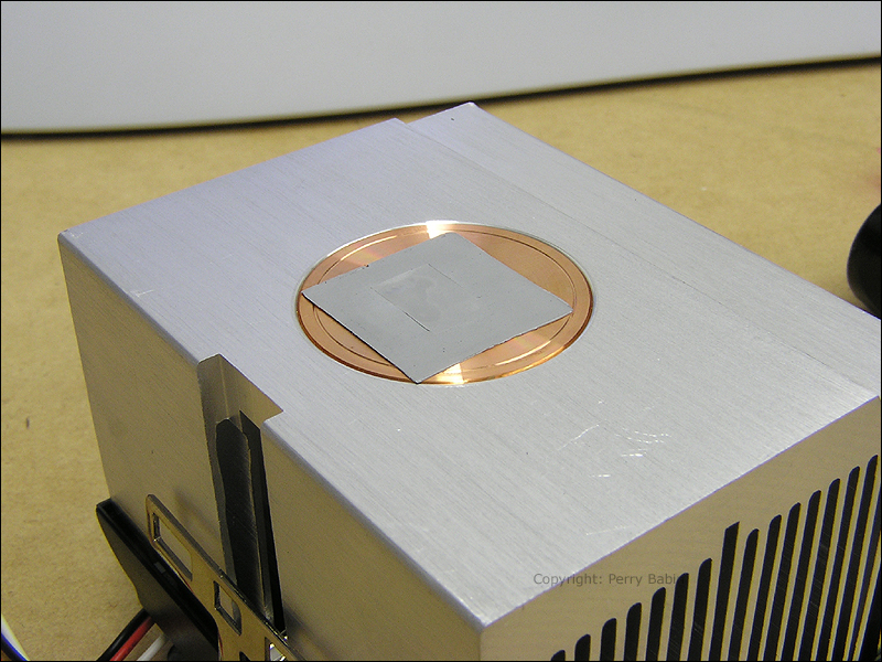
The HeatSink and Fan (HSF) below has a thermal pad covering the target area for the processor. The thermal pad is designed to conduct heat from the CPU to the heatsink. It is used to fill in tiny imperfections in the two components that would otherwise be filled with air (which is not an effective thermal conductor).
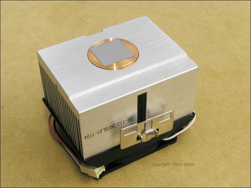 Don't try this at home... I removed the heatsink after mounting it to show you what happens to the thermal pad. I didn't run the processor with this thermal pad. If I would have, the indention would be much deeper and you would have been able to see the copper of the heatsink through it. When I install the processor later, I will be removing the pad to use a better, thermally conductive compound. After mounting the HSF onto the processor, you can not remove it. If you do remove it, you must either replace the pad or use some other thermally conductive material between the sink and the CPU. If you try to reuse the pad, it's unlikely that you will get adequate thermal conductivity from the used pad and the processor may overheat (and possibly fail).
Below, you can see the CPU and socket from the side. Notice that the socket had a raised area on the right side of the picture. This area houses part of the mechanism that locks/unlocks the CPU. If you look at the HSF, you can see a corresponding cutout.
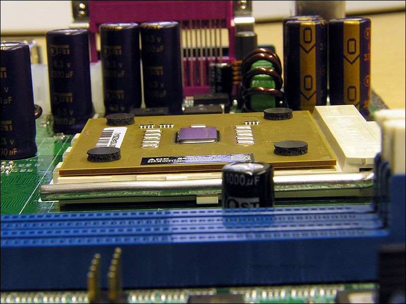 If you look at the angle of the HSF vs the processor, you can see that the HSF isn't sitting level. That's because the cutout in the heatsink is on the wrong side. It IS possible to clamp the HSF to the processor like this but the processor will not be in contact with the HSF and will overheat (and probably fail). When mounting the HSF be sure to set it the right way.
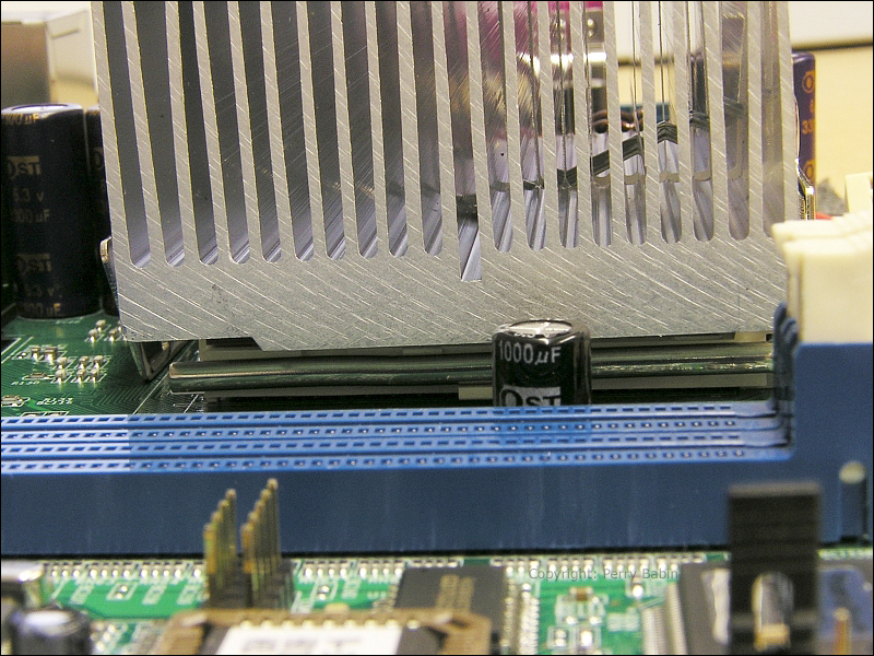 Here, the HSF is oriented properly.
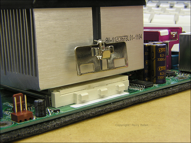
 In the next image, you see the HSF in place but it's not locked down. To maintain good physical contact between the HSF and the processor, a spring-loaded clamp is used. On the socket, there are three protrusions. These correspond to three slots in the spring clamp. The other side of the socket is made the same way.
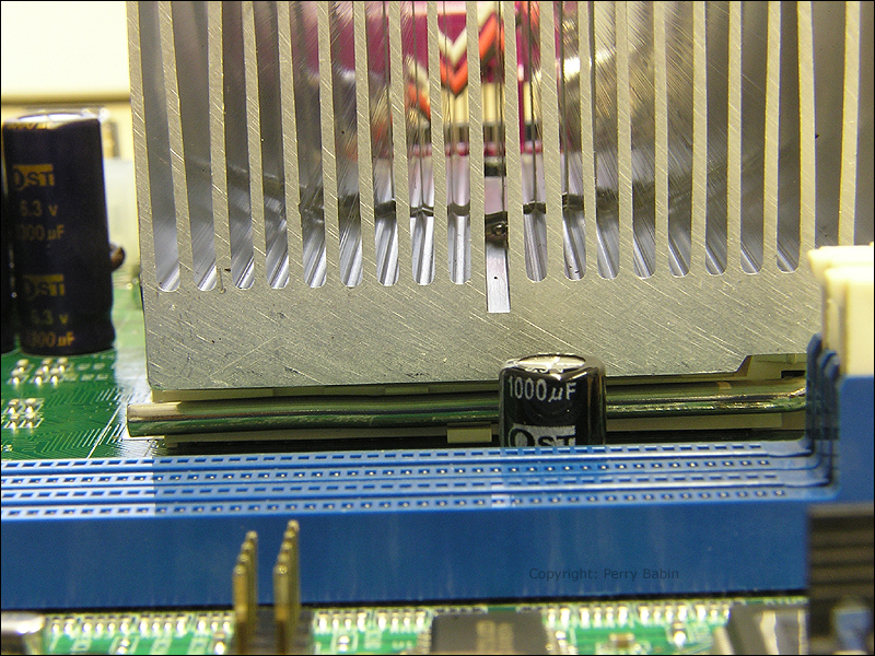
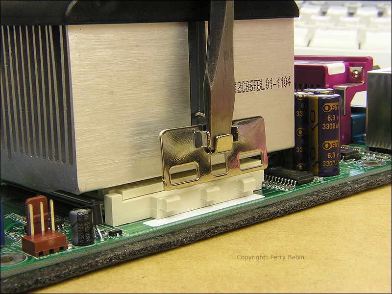
 To get the spring clamp into place you use a screwdriver as shown below. You gently pry the clamp outwards so that you can get over the protrusions on the socket. Then you slowly release it so that the clamp falls into the notches on the protrusions.
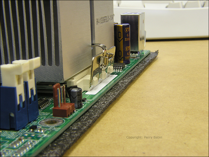
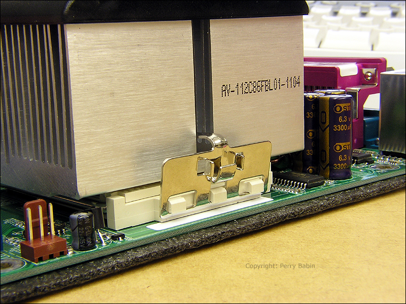 Above and below, you can see the clamp in place from 2 different angles. Make sure that you catch all three protrusions. If you don't, the clamp may break the socket which may render the motherboard useless.
Model: AMD Sempron 2800+
Core: Thorton
Operating Frequency: 2.0 GHz
FSB: 333MHz
Cache: L1/64K+64K; L2/ 256KB
Voltage: 1.65V
Process: 0.13Micron
Socket: Socket A Silicon Wafer:
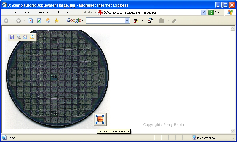
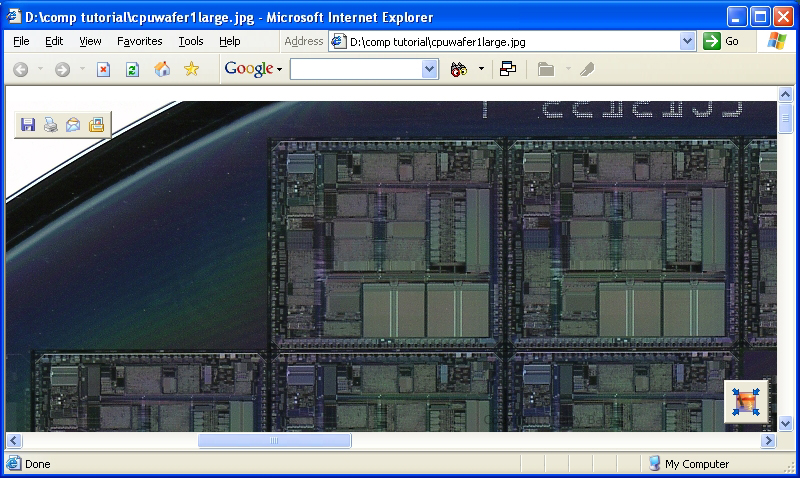
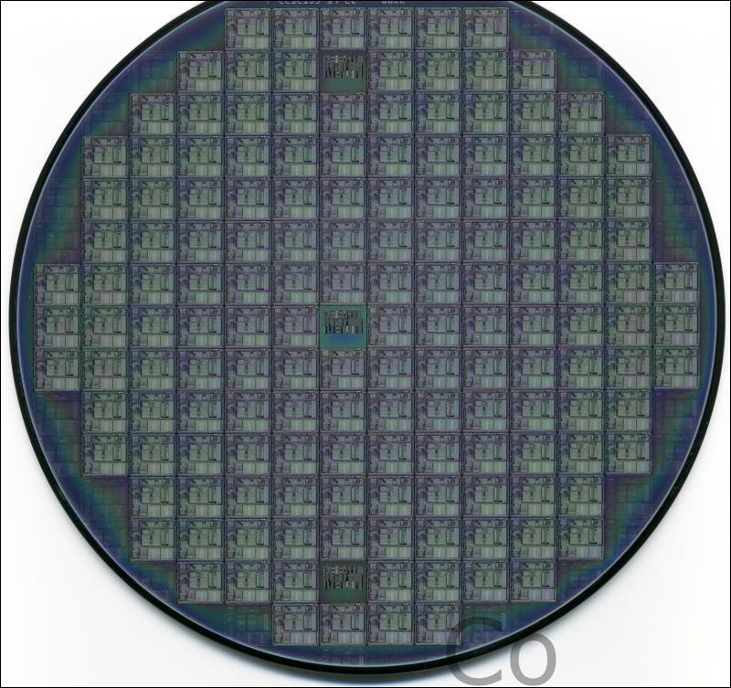 Click HERE to see a very large view of the wafer (scanned at 4800dpi). If your browser displays it properly, you will not be able to see all of it at one time. On my monitor, it looks to be approximately 3 feet across. If your browser resizes it, hold your mouse over the image until the browser resize button appears in the lower right-hand corner of the image. When the button appears, click it. When the image appears at full size, you will only be able to see a small corner of it (similar to that which you see in the second image below). Use the scrollbars to view other areas of the wafer.
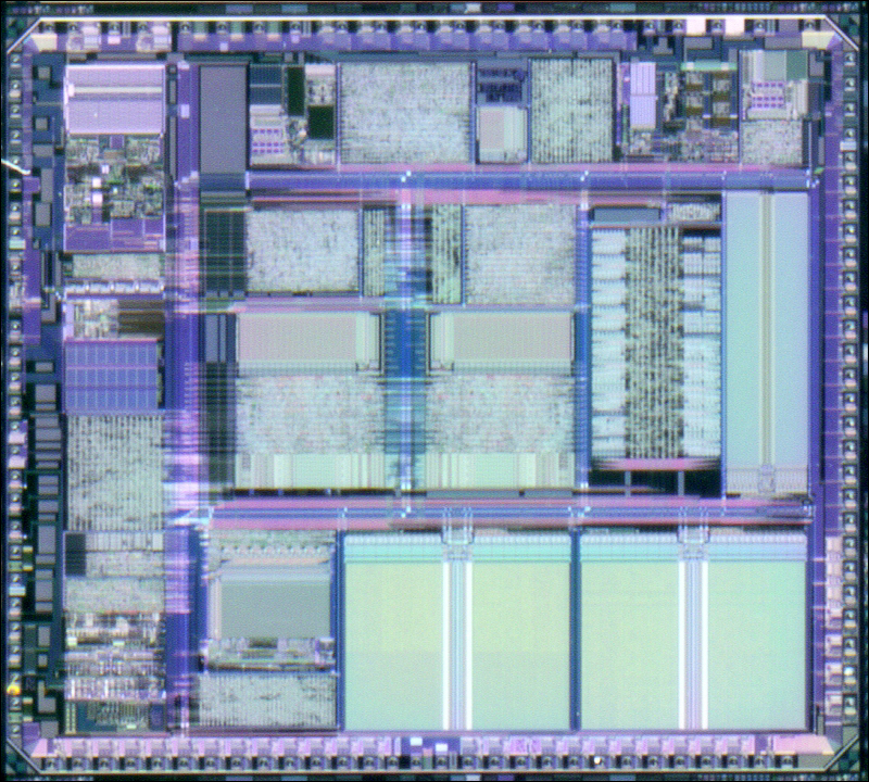
 Below is an enlarged view of a single processor.
|
|
| Contact Me: babin_perry@yahoo.com | |
|
Perry Babin 2005 - Present All Rights Reserved
|