|
The BIOS
|
|
Overview:
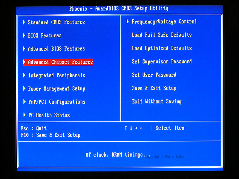
This is the first page you'll see when you get into this particular BIOS. The appearance and features of the various BIOS configurations from various manufacturers vary significantly. This is a Phoenix/Award BIOS. Some computers use an AMI BIOS. Other computer manufacturers produce their own BIOS software/firmware.
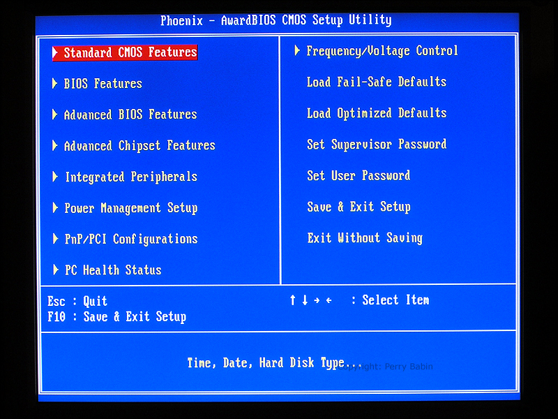 Above, you can see that the 'Standard CMOS Features' is selected. If you hit the ENTER key, you get the screen below. This is the screen where you set the system clock and set several of the drive parameters. Luckily, most of the newer BIOS' set/read the drive parameters automatically.
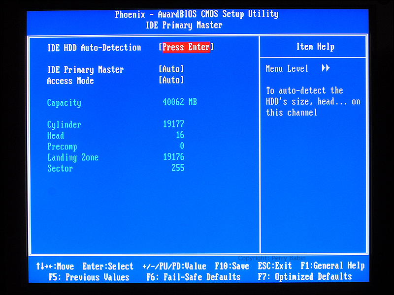
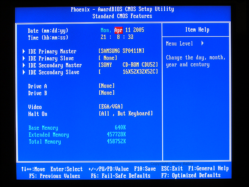 On the screen above, I scrolled down to the 'Primary IDE Drive' and hit ENTER. The next screen is the result. In this machine, the primary IDE drive is a 40GB Samsung drive. The screen shows the various drive parameters. Here, we want to let the BIOS set the parameters if the drive is capable. Some older drives don't have the capability to communicate that information to the BIOS and the parameters have to be set manually. Thankfully, most of the older drives have been taken out of service.
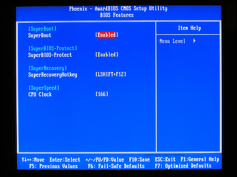
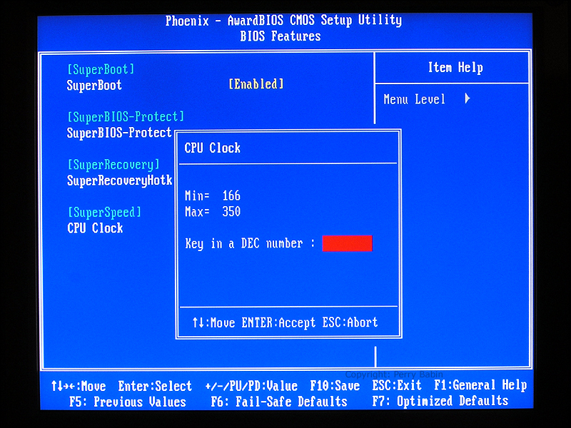
 Next, we scroll down to what is simply labeled 'BIOS Features' and click ENTER.
 Here you can see some relatively new/unique BIOS features. Super-boot allows the computer to start faster by storing certain basic system information in memory. The Super BIOS protect protects the computer's BIOS information from malicious software that tries to destroy the BIOS data. If the BIOS information is completely destroyed, the computer can not be booted and, if the BIOS IC isn't replaceable (installed in a socket vs soldered in place), the motherboard has to be replaced. The SuperRecovery allows you to partition off the drive in a way that nothing can access it from the OS (nothing -- not partitioning software or malware -- nothing). It is supposed to offer the highest level of protection for your data. The
 This is an image of the initial SuperRecovery screen.
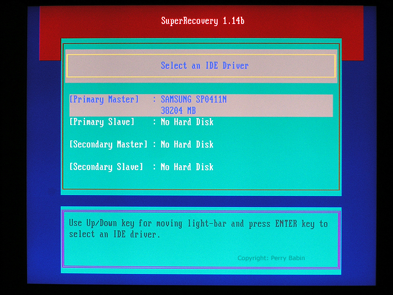 The next feature is the SuperSpeed feature. It allows you to increase the speed of the processor but you have to be careful. If you set it too high, your computer may become unstable, it may be unable to boot and/or it could overheat. If you ever make a BIOS change that prevents the computer from booting, you can clear the CMOS memory with the 'clear CMOS' jumper. Generally, this presents no serious problem (except for all of the settings going back to the default settings). However, in some cases where a RAID array is set up in the BIOS, the recovery takes longer. If you're working with a RAID, it may take several trips through the BIOS and several reboots to get things back in order (don't ask me how I know :).
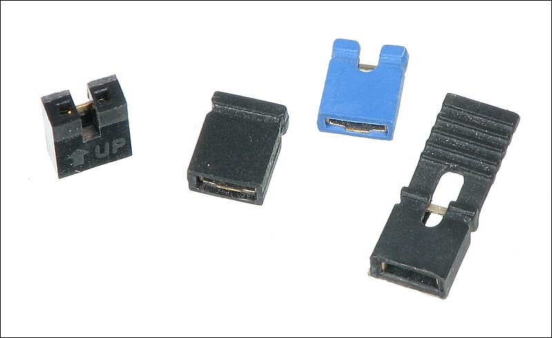
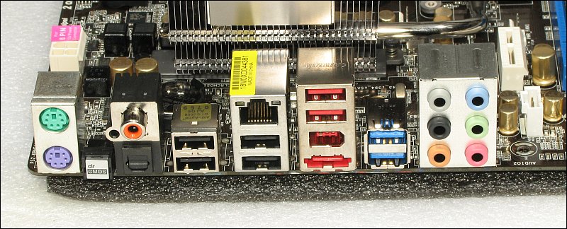
 Below is a picture of the 'clear CMOS' jumper (inside the dotted yellow line). It's generally very near the BIOS IC. If you ever need to clear the CMOS memory, you simply remove power from the computer, move the jumper from pins 1 and 2 to pins 2 and 3. After a second, return the jumper to pins 1 and 2 and restart the computer. The BIOS settings will now be as they were when you initially powered up the machine. In the following image, the green arrow points to the BIOS IC. On this board, it's soldered directly to the board but these are often installed in sockets to allow quick replacement. The orange arrow points to the backup battery. This retains the CMOS settings when no power is applied to the motherboard. The battery rarely needs replacing but if you're working on an old machine, you should check it to confirm that its voltage is approximately the rated voltage (generally 3v). The yellow arrow points to the clear CMOS header. As you can see, a shunt is installed across pins 1 and 2. If you're unsure about the pin numbering on a header, there are often indicators like the white triangle (red arrow). On this board, there is also a number 3 but there aren't always numbers.
You can click HERE to open it in a new window.
A couple more notes about the CMOS. As was stated previously, clearing the CMOS memory restores the system to what it was when the system was powered up for the first time. Generally, the computer will function after clearing the CMOS but for advanced systems there are some things you should know.
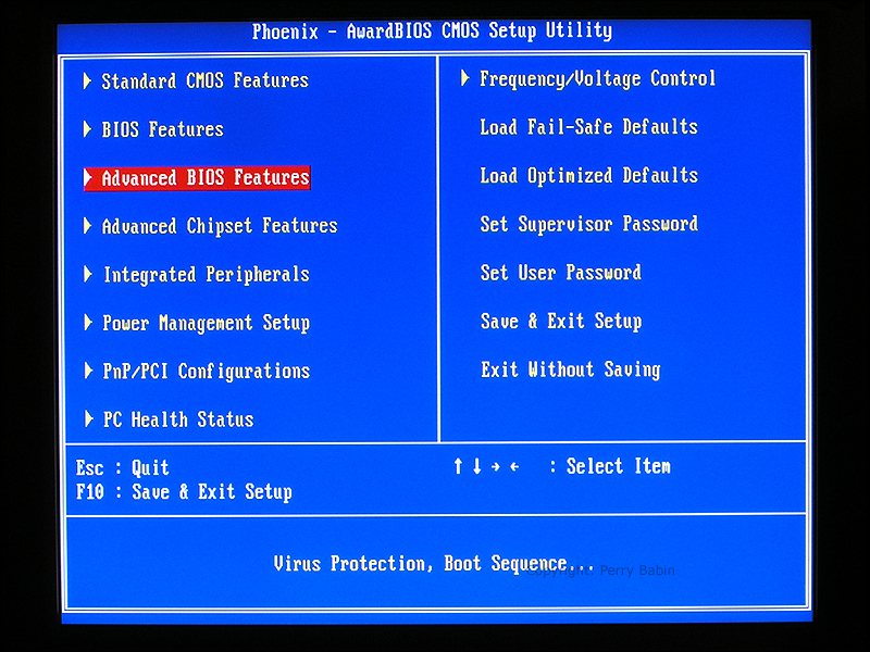
Here, we scrolled down to the 'Advanced BIOS Features' and clicked enter.
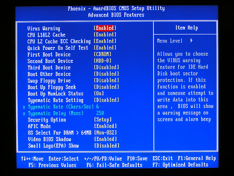
 There are too many features here to cover them all but you should notice a few. At the top, you can see that the virus warning is ENABLED. The 'quick POST' is enabled (allowing even faster booting). Below that, you can see that you have options for the boot order of the various drives. Here, we have told the computer to boot to the CD ROM first and if you don't find a boot record, boot from the hard drive. To shave a few seconds off of the boot time, you can have it boot to the hard drive first but if you need to run something like True Image recovery, you will need to go into the BIOS and set it to boot from the CD ROM first.
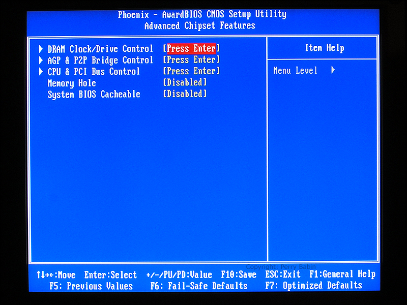
 Next, we enter the 'Advanced Chipset Features'.
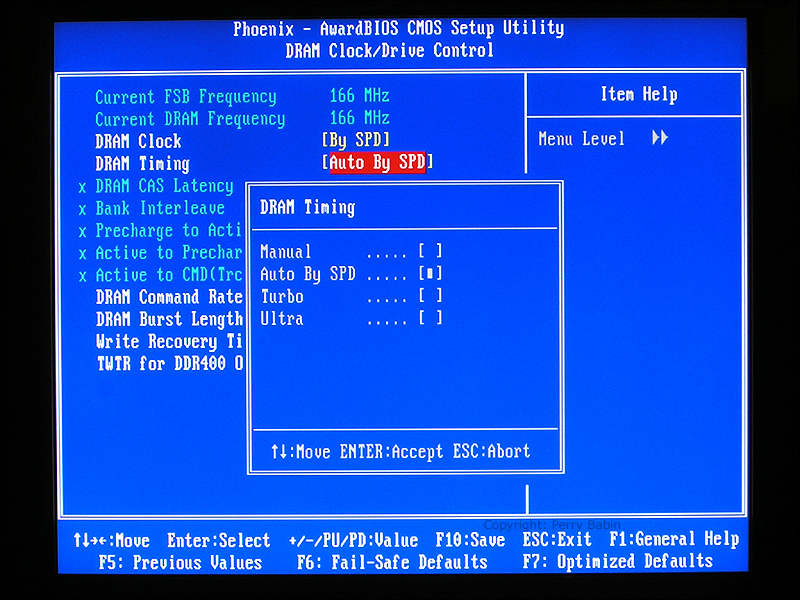
 And on the 'Advanced Chipset Features' page, we enter the DRAM control page.
 Here, we can control the FSB (Front Side Bus) clock frequency. If we set it higher than the CPU's rated FSB clock frequency, the system may run somewhat faster but it may also become unstable (crashing/locking up). You may also notice the SPD entries. SPD stands for Serial Presence Detect. The SPD is information about the memory. This information is used by the BIOS to set the proper memory parameters.
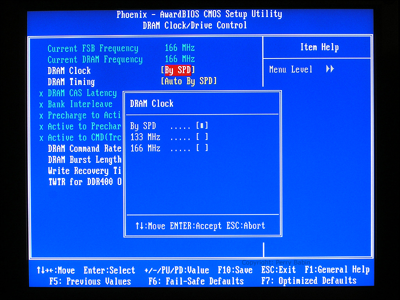
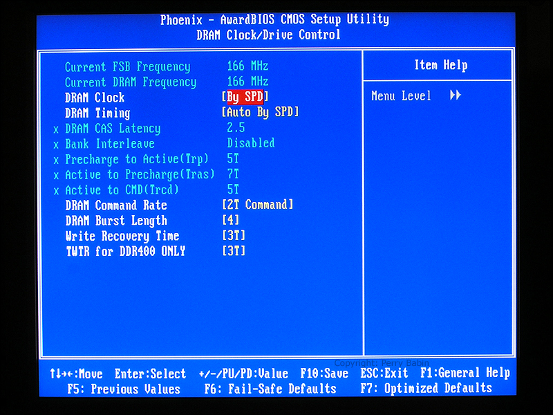 In the DRAM clock section, you can see that there are three choices. In some situations, you may want to overclock/underclock the memory. Here, there is no overclocking. For the best stability, you should set it to 'By SPD'.
 Below, you can see the 'DRAM Timing' dialog box. The 'timing' is the number of clock pulses between certain events in the memory's operation. When overclocking, these numbers become important in getting the best possible performance. For this computer, the best setting is 'Auto By SPD'.
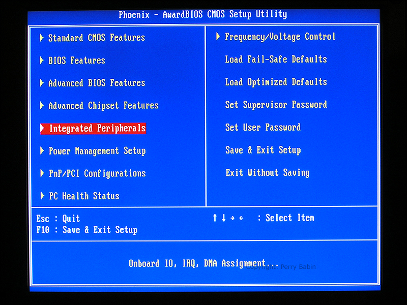
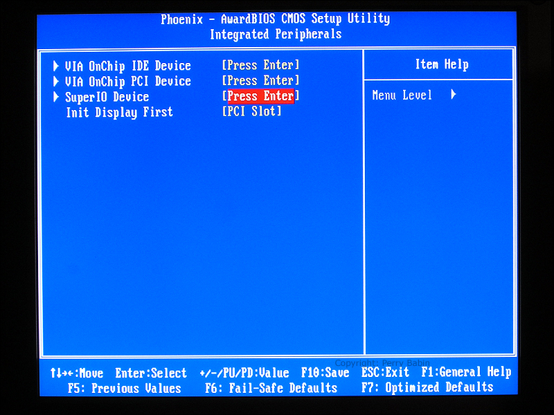
 The 'Integrated Peripherals' page deals with the parameters of the drive and PCI controllers.
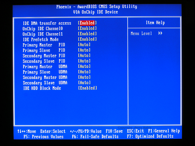
 Here, we enter the IDE device page.
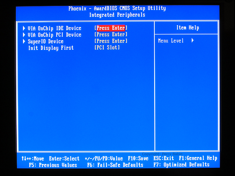 Below, you can see several of the choices. Some drives have to operate in PIO (Programmed Input/Output) mode and others can operate in DMA mode. All of the settings are set to auto here. When a drive operates in PIO mode, all of the data passes through the processor. In DMA (Direct Memory Access), the processor is bypassed and the drives can communicate with the memory directly. This is much more efficient and it frees up the processor.
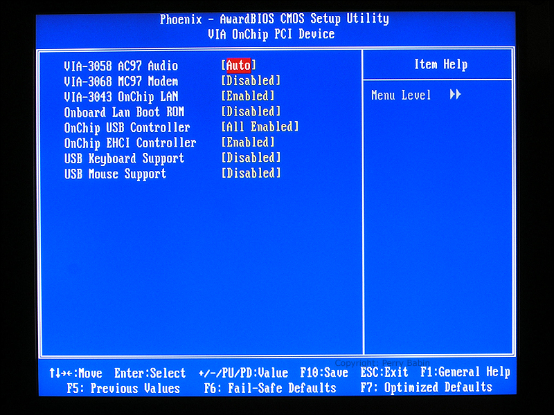
 This page allows you to enable/disable several functions. The specific functions that you'll need are dependent on the system you're building.
 Here, we will enter the Super IO page.
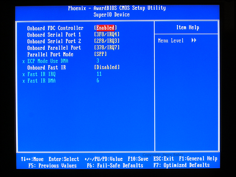
 The Super IO IC is the interface between the southbridge and the serial, parallel and IR (InfraRed) ports.
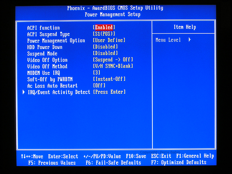
 Below, we enter the 'Power Management' section.
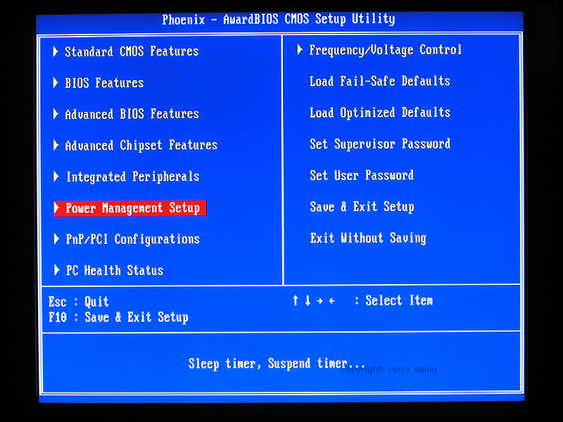 Here, we can determine how/when the computer shuts down after a period of inactivity. This page allows you to control the way the computer shuts down. There are options for when you use the power button to shut the computer down and when the computer is shut down automatically.
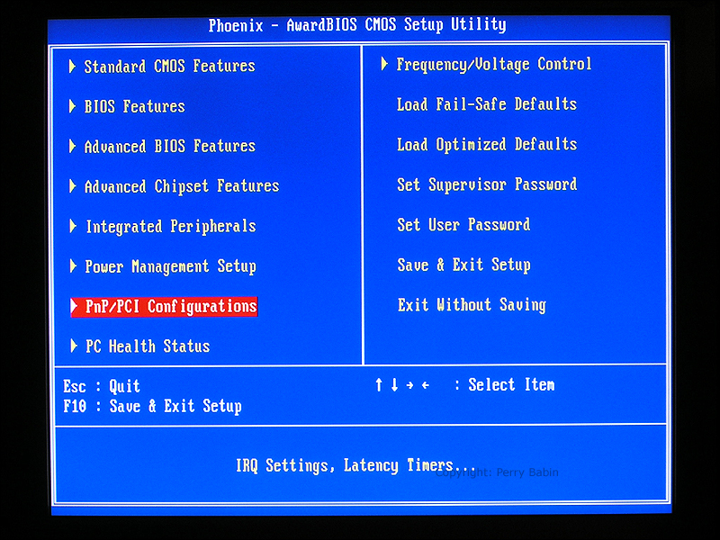
 Here we enter the PNP (Plug and Play) page.
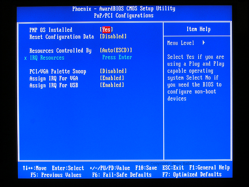
 On this page you can see a setting that needs to be changed. The PNP OS should be set to no. This seems counterintuitive (it is actually, if you ask me). When set to yes, the BIOS leaves it to the OS to resolve IRQ conflicts. This is better done outside of the OS so the proper setting should be no.
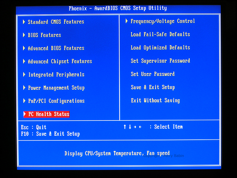
 Here we enter the 'PC Health Status' page.
 This page tells you several things including the processor's core temperature, the system temperature, the operating speed of two fans and two of the power supply voltages. The CPU core voltage is not produced directly by the computer's switching power supply. It is converted from one of the power supply outputs by a switching regulator. You should remember the pictures earlier of the PWM FETs that were located near the CPU socket.
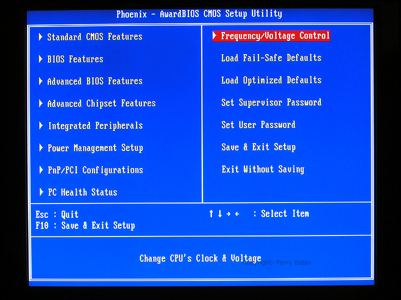
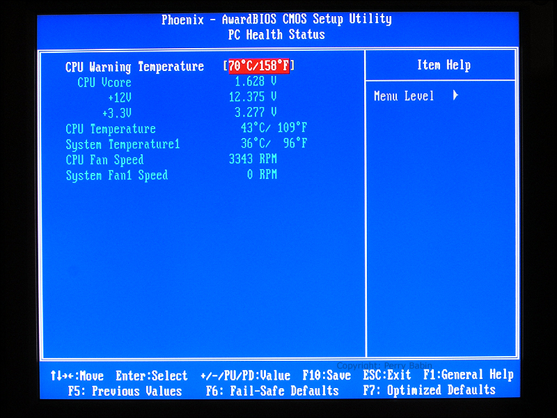 Note: When starting a newly assembled system, it's a good idea to visit this page (above) as soon as you boot the system. If the CPU temperature is above ~60c, there is very likely you haven't properly mated the heatsink to the CPU. While it's possible for a processor to run at 60c (60 degrees celcius) under a heavy load, it should not run that hot at idle. If your processor is running hot, shut it down and check the heatsink mounting. If you can't see it directly, a small mirror and a flashlight will usually help. Be sure that the computer is unplugged from the wall outlet when you are working inside the cabinet. While there is only low voltage present, if you accidentally short anything with the system powered up, you may do serious damage. Remember that there is at least one 5 volt supply that has voltage even when the computer is off. Here we enter the 'Frequency/Voltage Control' page.
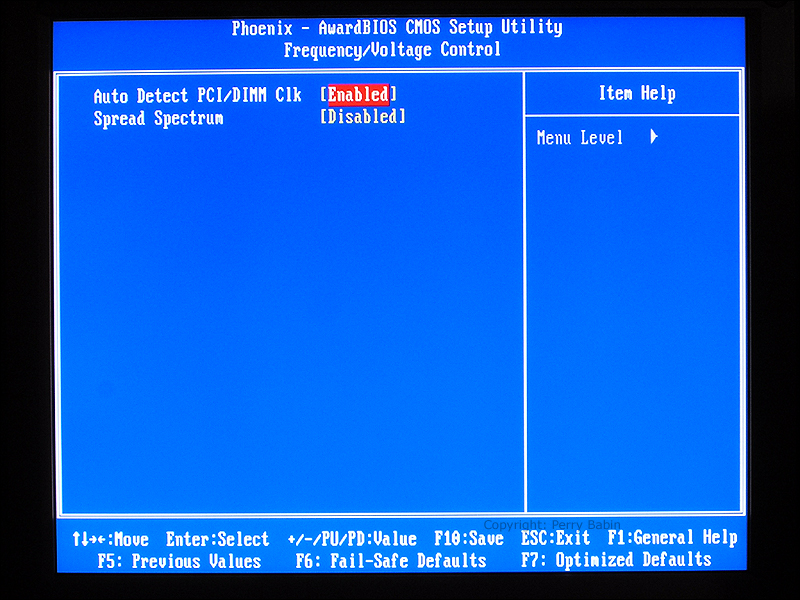
 The 'auto Detect' setting determines whether the system clock (oscillator not time clock) is on or off when there is no memory or PCI card in the slot. The 'Spread Spectrum' setting controls whether the clock frequency is constant or varying. When the clock frequency remains constant, more energy is concentrated at one frequency and therefore more likely to produce interference in other devices.
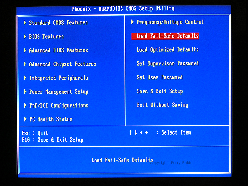
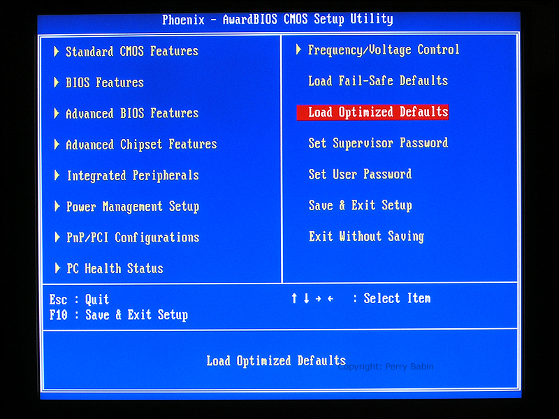
 The 'Load Fail-safes' option will set all of the BIOS parameters to the settings that are least likely to cause problems. If set to the fail-safes, the system will not perform up to its full potential.
 This is similar the the fail-safes settings but it sets the BIOS parameters to those which are most likely to provide the most stable operation.
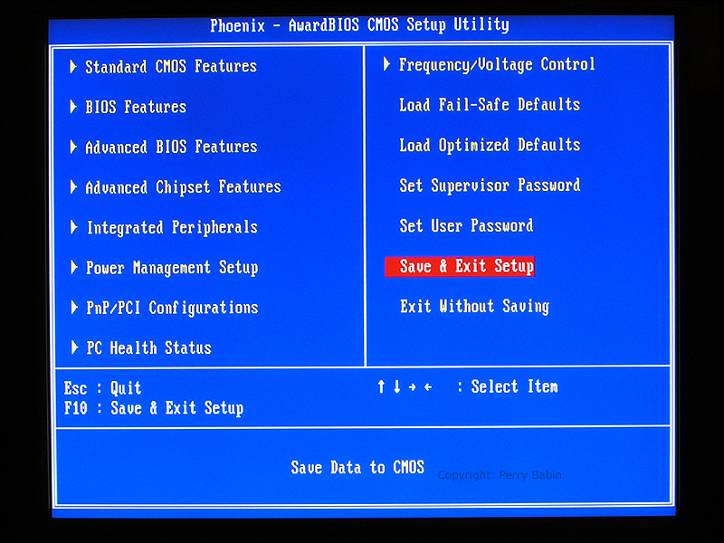
 To save the new values and exit, you can either scroll to here and hit ENTER or you can hit F10.
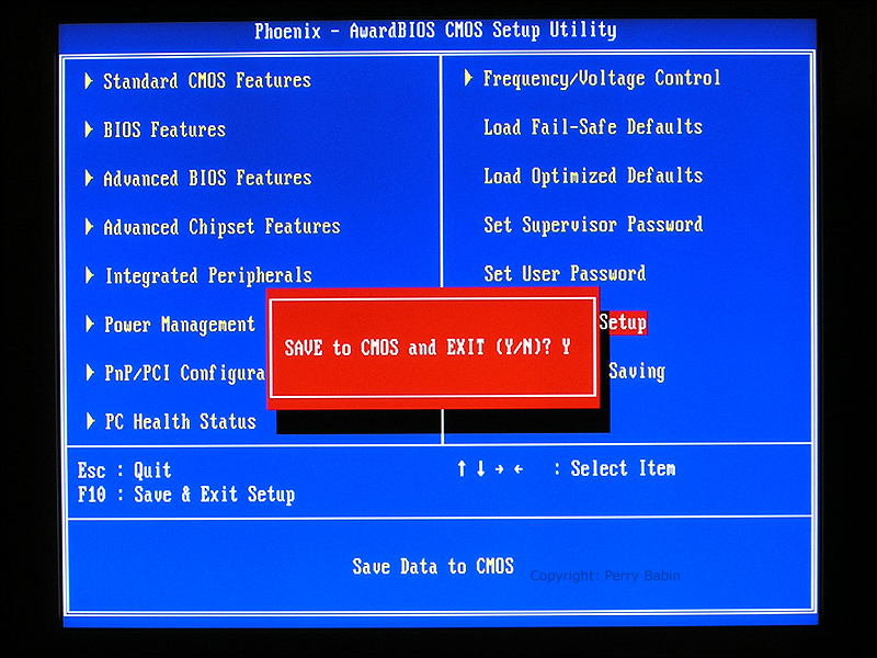
 When it asks you if you want to exit and save, you must enter 'Y' instead of 'N'.
 Flashing the BIOS: Note: Flashing the BIOS can be dangerous. If power fails or you get a 'bad flash', your motherboard could be rendered useless. It's only advisable to update the firmware when absolutely necessary. Even then, you should use a UPS (Uninterruptable Power Supply) to protect against power failure.
The following is not exactly a step_by_step tutorial but it will show you basically what's involved with a raid setup. If Windows (or any operating system) is to be installed on the RAID array, this must be done BEFORE the installation of the OS. On the 'XP Installation page', I show how the SATA RAID drivers are installed but this is different. This sets up multiple drives to act as one drive (in the case of a RAID 0 configuration). The driver installation on the XP installation page gives Windows the information it needs to operate the SATA interface. In this case, the SATA interface is where the RAID drives will be connected to the motherboard. There are some boards where the IDE drives can also be used in the RAID array but that's not possible with this board.
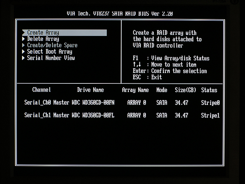
When your computer boots, it will get to a screen that allows you to enter the RAID setup utility. If it doesn't, you may have to enable it in the BIOS. This one was set up to automatically display the option to enter the utility. It doesn't stay on this page for long so you have to be ready to hit whatever key is required to enter the utility. Here, the 'tab' key is used.
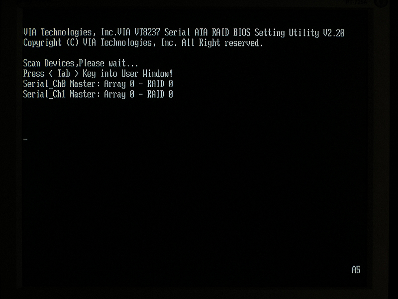 When you enter the utility, you will see something similar to the following screen. Here, you will select the drives you want to use in the array and you will choose the type of array (RAID 0 was chosen for this array). When you finish here, you will need to reboot.
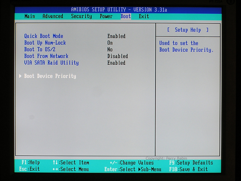
 After rebooting, on this computer, I had to go into the BIOS (after setting up the RAID array) and set the boot priority. I couldn't select the array BEFORE it was set up. That's why we had to reboot to setup this option. Here, I went to the BOOT tab and scrolled down (arrow keys) until I selected the 'Boot Device Priority' option. Then I hit the enter key to enter the boot priority page.
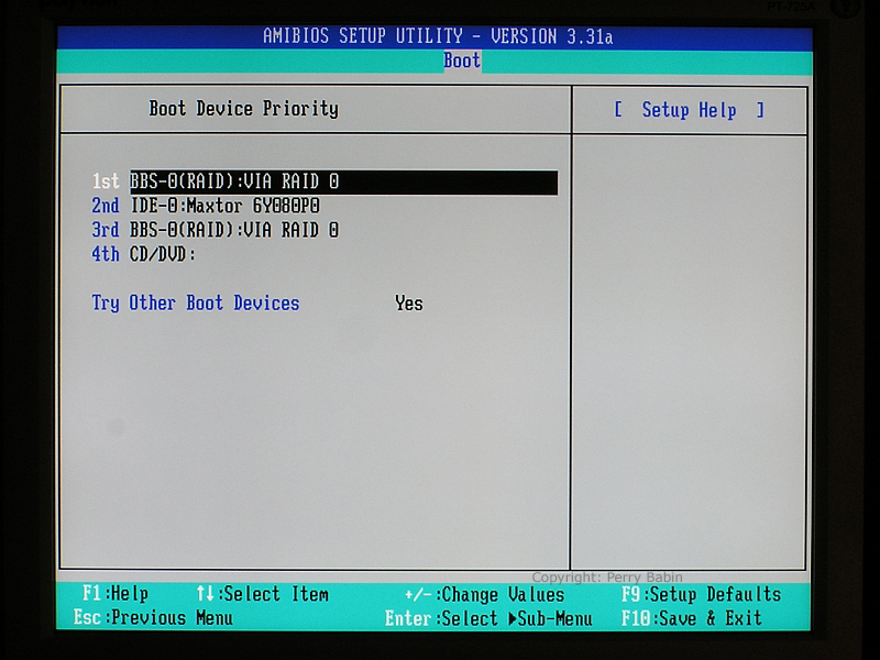
 I want it to boot to the array so I set it as the first on the list. As you can see, the array is listed twice. It doesn't matter but ideally it would only be shown once. The third selection should be CD ROM (if that's what you want) and the fourth would be blank or disabled. When booting, the computer looks for the OS on the top drive. If it's not found, it continues looking for a bootable OS until it finds one or until it runs out of choices.
 After making the desired changes, make sure you save them. You will exit the BIOS as we did on the previous BIOS example (F10). Be sure that you choose the 'Y' option instead of the 'N' option.
|
||
| Contact Me: babin_perry@yahoo.com | ||
|
Perry Babin 2005 - Present All Rights Reserved
|