Overview:
This is a linear voltage regulator designed to allow the user to set the speed of their fans (typically those used to cool their amplifiers). There will be two different versions. One is able to easily control 2-3 standard brushless fans. The other (which varies just slightly) can handle ~6-8 amps of current continuously. The higher current version requires a much larger heatsink and a different transistor at the output stage. The high current version uses a fan cooled heatsink like those used to cool AMD or Pentium processors. You can use one that was pulled from an old computer or you can purchase a new one. A new heatsink and fan can be purchased for ~$10. The high current version will work perfectly well for low current but it's more expensive and will require a little more assembly time because the heatsink will have to be drilled to accept the mounting hardware.
General specs:
This regulator can hold the set-point voltage (as read with a DC voltmeter) to well within 1% of the set-point with an input voltage as low as the set-point voltage plus ~3% of the set-point voltage at 1 amp of output current. This means that is can maintain an output voltage of 11 volts with an input voltage of 11.33 volts. Of course, under heavier loads, it will require slightly more margin to maintain the set-point voltage. The output voltage can be set from ~1 volt to ~+B input. Again, the maximum output voltage will be determined by the input voltage and the output current. The minimum input voltage is ~6.5 volts. The regulator will work below 6.5v but variations in input voltage will likely cause variations in output voltage.
The regulation is typically within 1% at the output of the regulator (the DC resistance of the wiring would be the most likely cause of a higher voltage drop at the load). For example, if the regulated voltage set-point is 10.25 volts at 0.5A of current, the output voltage will not vary by more than 1% if the load is increased (more fans...) and the current draw increases to 4 amps. This means that the voltage will no lower than ~10.15 volts at 4 amps (the voltage typically drops a bit under heavier loads).
Protection:
The recommended fuse size is 5A. I've tested the regulator by shorting a 7.5A fuse across the outputs and it survived. If you're only going to need 1-2 amps of current, you may want to use a 3A fuse for an even better safety margin. The transistors can easily handle 7.5A of current but at high temperatures, their current handling capacity is significantly reduced.
Electrical Isolation:
When you fasten the transistor to the heatsink, you need to decide whether you want to have the transistor electrically isolated from the heatsink or not. If the transistor is mounted directly to the heatsink, the heat transfer will be better but you will need to isolate the heatsink from ground. If the non-isolated heatsink comes in contact with ground, the output transistor may be damaged. If the heatsink is insulated from the transistor, the transistor will run slightly warmer (but not so warm that it will fail). Using two parallel transistors will reduce operating temperature of the individual transistors (if you have sufficient heatsinking).
If you decide to build the high current version and want electrical isolation from the heatsink, I'd suggest using mica or aluminum oxide insulators. The following is a link to the aluminum oxide insulators:
http://www.mouser.com/
Thermal Compensation:
If you want/need temperature control, you can parallel an NTC thermistor across the 10k ohm resistor. If the thermistor is placed on an amplifier (or anything else that's being cooled by the fans that are controlled by the regulator), the speed will vary with the temperature to regulate the temperature of the amplifier. As the temperature increases, the resistance of the thermistor is reduced. When in parallel with the 10k ohm feedback resistor, this increases the gain of the circuit which increases the output voltage and therefore the speed of the fans. Note that the thermistor needs to have good thermal contact with the amplifier's heatsink. If the thermistor is simply touching the amp, there will be little thermal conductivity between the amp and the thermistor. If the thermistor is in the path of the air flow, the thermistor will be cooled by the moving air. To assure that the thermistor is close to the temperature of the amp, you can use heatsink compound between the sink and the thermistor. To keep the thermistor out of the air flow, you could mount it under the amplifier (in a shallow indention so it's not crushed by the amp).
Thermal Protection:
The most basic version of this regulator has no thermal protection so you should monitor it's operating temperature under most all ambient temperature conditions. If the heatsink gets too hot to continuously hold with your hand, it's running too hot. For it to run cooler, you can do any of the following:
- Use a larger heatsink
- Provide more air flow over the heatsink (a tiny 50mm fan blowing across the heatsink will bring the temperature down significantly)
- Reduce the load
- Lower the input voltage to the regulator (not an option in most cases)
If you want to add thermal protection, page 6 of the schematic file in the 'circuit design' section below shows the required circuitry.
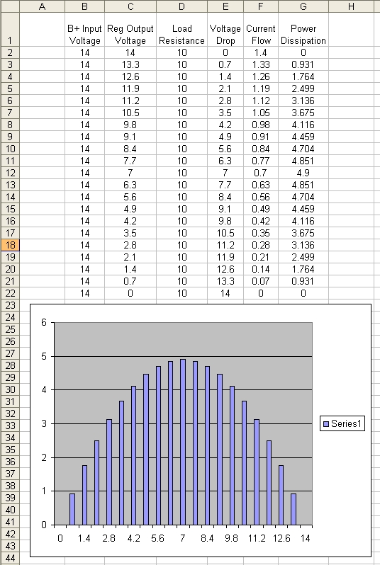
Power Dissipation and Heat:
The temperature of the output transistor is dependant on several things. From the list above, you can see several things that can affect the temperature. In virtually any electronic device, the power dissipation is determined by the current flow through the device and the voltage across the device. According to Ohm's law, the power dissipation is equal to current mulitplied by voltage. This means that the temperature of the output transistor will vary with current flow and voltage drop.
Let's say that we have the following parameters...
- input voltage: 14 volts DC
- Output voltage 8 volts DC
- Load current at the regulated voltage: 0.75 amps
This means that we have 6 volts of voltage drop across the output transistor. If we use the formula P=I*E, we find that we have 4.5 watts of heat. If we change the output voltage of the regulator to the maximum possible, you would have approximately the following parameters:
- input voltage: 14 volts DC
- Output voltage 13.9 volts DC
- Load current at the regulated voltage: 1.30 amps
The power dissipation would be approximately 0.13 watts. Compared to the previous example where the regulator was dropping 6 volts, there is much less power dissipation and the regulator would run much cooler. The following graph shows how power dissipation varies with varying output voltages. The vertical axis is power dissipation. The horizontal axis is the voltage drop across the device. You can see that the power dissipation is greatest when the voltage drop across the output transistor is ~1/2 of B+.
Circuit Design:
The following Flash file contains a schematic for the fan speed regulator. Page 2 of the file matches images of real components with the schematic pins. Page 3 shows the voltage at several key points in the circuit. Page 4 shows a modification that allows the regulator to vary the output with temperature. More details are available on each page. Remember that you can use the right-click to zoom in on the Flash file. Click HERE to open it in a new window. Maximize the new window to make it as large as possible. F11 will toggle full screen mode.
High/Low Power Output Transistors/Heatsinks:
In the following image you can see the standard output transistor and heatsink and the high power version. The high power version can dissipate MUCH more power and can therefore handle heavier loads. The larger version has its own fan. The fan will significantly reduce operating temperatures and is required when using the regulator to supply more than a few amps of current. As you can see, the heatsink has quite a bit of free space. If you want to add an extra margin of reliability, mount a second transistor on the heatsink. You'll simply wire them in parallel. The control circuit will have no problem driving the two FETs. In the photo, relatively small wire is soldered to the transistor. If you're going to drive a load that's going to draw more than a few amps of current, you'll need to use larger wire. For up to ~8 amps of current, 16g wire will suffice.
Below is a printable scan of a Radio Shack 276-168b circuit board. This is a good prototype board that works well for many projects This view of the board is as if the board were clear and you could see the copper on the bottom of the board. Use this enlarged version to layout component parts and jumpers before you begin soldering.