
|
| Email Home Page |
|
|
|
|
| Email Home Page |
|
|
|
The RCA cable, which is used in virtually all car audio installations, is a specialized cable which is designed to transmit audio while preventing noise from entering the audio stream. As you can see in the diagram below, the center conductor is "shielded" from noise by completely enveloping it in a braided copper shield conductor. The shield is connected to the reference terminal of the audio source. You remember that every measurement has to have a reference. The same is true when you are sending a signal (audio in this case). This is so because the next device in line must "measure" the level of the incoming signal. If it does not have a good reference, the signal quality will suffer. I will explain "audio grounds" in a section to come.
 I don't know if this is the best place for this but...
WARNING!
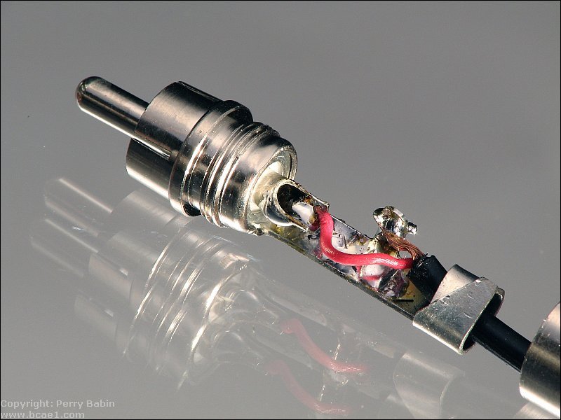
Making Your Own Cables:
 The following is approximately what your made-up connections should look like. There are a couple of things that can make this cable more reliable. The retention at the back of the connector is weak because this is thin cable. To make it a bit more durable, apply a bit of Goop or E6000 to the cable at that point. There is also no strain relief on these connectors. To produce a strain relief, you can use heatshrink tubing. This was shown on the Installation Primer page. When making up cables, it's common to forget to place the cover for the RCA plug on the cable before the last connector is soldered on. This is VERY annoying. Don't forget to do this when making up your cables.
 Not all connectors are reliable. When I need a connector that will last for a long time, I use Switchcraft connectors. The last cables I made up for my test bench lasted for more than 5 years and were used repeatedly every day. I made up a temporary set from some metal plugs from Radio Shack and they both had intermittent connections between the shield connector (where the wire solders to the connector, internally) and the actual shield on the plug. Of course, it didn't get noticed until after all of the heatshrink tubing and Goop was applied so it couldn't be repaired. They will have to be cut off and replaced. |

|

|
|

|