|
L-Pads
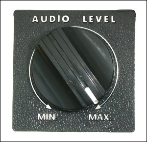 An L-pad is a passive device which lets you control the output level of speakers without changing the impedance seen by the amplifier. A constant impedance is not really necessary for the amplifier but if you are using passive crossovers, a constant impedance is necessary to prevent the crossover frequency from changing. The following image shows what typical L-pad looks like. This L-pad is relatively large (~3" in diameter) because it's rated at 100 watts. L-pads rated for higher power have to be larger than ones rated for lower power because they have to dissipate more heat. This one has an unusually long shaft. This would generally be installed directly into the wall of the speaker enclosure. If you were using a terminal cup, you could use this (using nuts to allow only a fraction of the shaft to protrude through the terminal cup but it would be better to use one with a proper/short shaft.
Construction:
An L-pad consists of 2 resistors connected by a movable terminal (the 'wiper'). One resistor is in series with the load and the other (shunt) resistor is connected in parallel with the load. The combination of the series resistance and the parallel shunt/speaker loads will always present a constant load to the amplifier. The diagram below shows the schematic symbol for an L-pad. You can also see that the 2 resistors are not the same value. The movable terminals vary the resistance in series with the speaker and also vary the resistance in parallel with the speaker load. The position of the wiper is determined by the position of the volume knob on the L-pad.
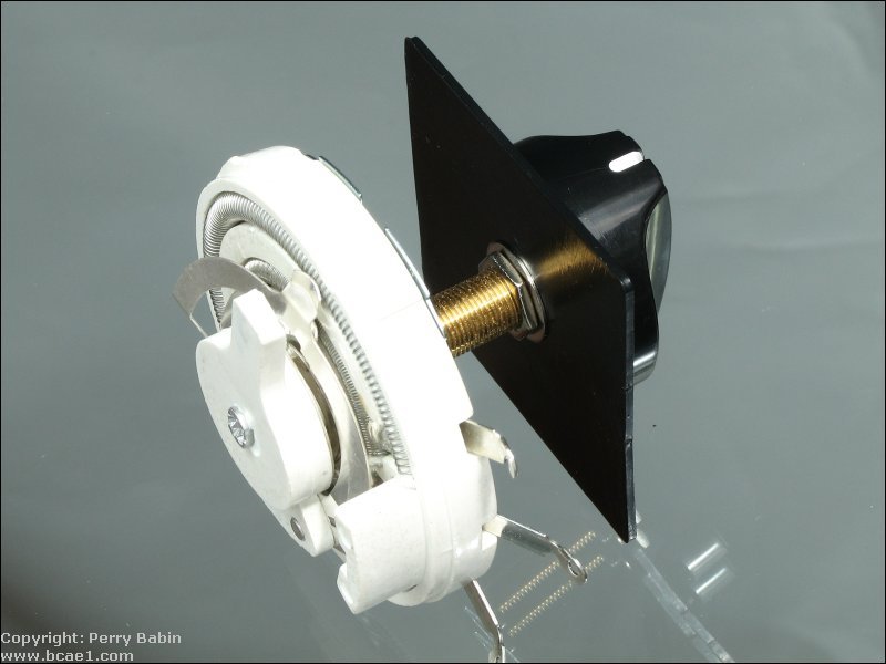
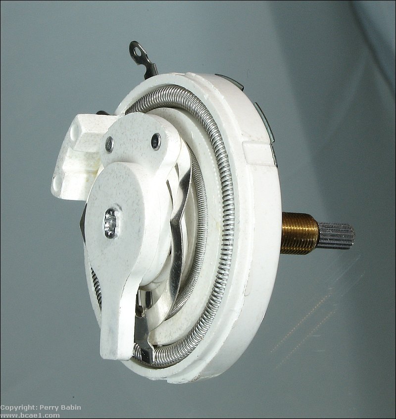
The following image shows the internal resistors and the wiper contact on the larger wirewound resistive element.
----- Critically Important -----
Adobe has deemed that the Flash content on web pages is too risky to be used by the general internet user. For virtually all modern browsers, support for Flash was eliminated on 1-1-2021. This means that those browsers will not display any of the interactive Flash demos/calculators/graphics on this (or any other) site.
The simplest (not the best) fix, for now, is to download the Ruffle extension for your browser. It will render the Flash files where they were previously blocked. In some browsers, you will have to click on the big 'play' button to make the Flash applets/graphics visible.
An alternative to Ruffle for viewing Flash content is to use an alternative browser like the older, portable version of Chrome (chromium), an older version of Safari for Windows or one of several other browsers. More information on Flash capable browsers can be found HERE. It's not quite as simple as Ruffle but anyone even moderately familiar with the Windows Control Panel and installation of software can use Flash as it was intended.
Connection:
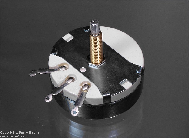
An L-pad will generally have 3 or 4 terminals. For the ones with 4 terminals, two terminals are provided for the negative (one for the amp connection and one for the speaker connection). The amplifier's speaker output terminals are connected to the outer terminals of the L-pad. The speaker's positive terminal is connected to the wiper. The speaker's negative wire is connected to the same terminal as the amplifier's negative speaker terminal.
![]()
Click HERE to open this graphic in a new tab. Right-click to zoom. Left-click to drag.
Level control:
This diagram shows how the output level corresponds to the wiper position. You can see that when the wiper is closer to the amplifier positive out terminal, the output is greater than when the wiper is close to the amplifier's negative output terminal. With the L-pad in the fully clockwise position, the wiper is directly connected to the positive terminal of the amplifier and there is no connection to the shunt resistor. When the L-pad is in the fully counter-clockwise position, the wiper (remember it's connected to the speaker's positive terminal) is connected directly to the negative terminal which means that the speaker can produce absolutely no output.
Click HERE to open this graphic in a new tab. Right-click to zoom. Left-click to drag.
How does it do it?
The table below shows how the shunt and series resistances (in conjunction with the speaker) maintain a constant load even though the power getting to the speaker is not constant. The table shows the values of the resistors starting at the maximum level (at the top) and ending with zero volume.
| Speaker load |
Series
resistance |
Speaker and
shunt
in parallel |
Shunt value |
Load presented
to amplifier |
| 8 ohms | 0 ohms | 8 ohms | open | 8 ohms |
| 8 ohms | .5 ohms | 7.5 ohms | 120 ohms | 8 ohms |
| 8 ohms | 2 ohms | 6 ohms | 24 ohms | 8 ohms |
| 8 ohms | 3.5 ohms | 4.5 ohms | 10.29 ohms | 8 ohms |
| 8 ohms | 5 ohms | 3 ohms | 4.8 ohms | 8 ohms |
| 8 ohms | 6.5 ohms | 1.5 ohms | 1.85 ohms | 8 ohms |
| 8 ohms | 8 ohms | 0 ohms | 0 ohms | 8 ohms |
|
The calculator below will allow you to calculate the series and shunt resistors as well as the power rating for the respective resistors. Don't try to find resistors with the same exact power rating as the calculator recommends. Those values are the minimum safe value with the given amplifier power. Use the next higher available power rating. The terms 'shunt resistor' and 'parallel resistor' are interchangeable. Don't let it confuse you.
Click HERE to open this graphic in a new tab. Right-click to zoom. Left-click to drag.
-
Notes:
-
The voltage across the series resistor plus the voltage across the shunt/speaker combination must equal the total voltage from the amplifier's output.
-
The current through the series resistor is equal to the current from the amplifier's output.
-
The current through the shunt plus the current through the speaker must equal the total current from the amplifier's output.
-
The power dissipated in the speaker plus the power dissipated in the shunt resistor plus the power dissipated in the series resistor must equal the amplifier power.
-
The combination shunt/speaker impedance plus the series resistance must equal the speaker's impedance. Remember that we're trying to reduce the output of the speaker without changing the impedance seen by the amplifier or passive crossover.
L-pad Sources:
Parts Express
Parts Express L-pad Page
|


