This page will contain circuits that I've been asked to build.
DISCLAIMER:
All of these circuits have been tested but you use them at your own risk.
Infrared Repeater
This is an infrared repeater. It is used to detect the signal from an infrared
remote and retransmit it from a second IR LED.
The red LED is the indicator LED. It tells you when the detector is picking up
the signal. It also lets you know if the output of the repeater is working
correctly. The darker LED is the IR LED. It must be placed in front of the
device which is to be controlled by the repeater.
PARTS LIST
R1: 1 ohm 1/4 watt or higher
R2: 1000 ohms 1/4 watt or higher
R3: 750 ohms 1/2 watt
R4: 15,000 ohms (critical) 1/8 watt or higher
R5: 75 - 100 ohms 1/4 watt or higher
C1: 1000pf (.001uf) (critical) ceramic capacitor not recommended
C2: 330uf - 1000uf electrolytic Radio Shack pt #  272-957
IR detector: Radio Shack pt # 276-137
IC1: TL594CN Source Farnell Electronics www.farnell.com 1-800-718-1997
IR LED: Radio Shack pt # 276-143
D1: 1N4001 or better
Notes:
***Most Importantly,
use a socket
for the TL594. If you accidentally destroy the 594 when working with it, you
would have to start over in most cases. With the socket, you can simply pop out
the old chip and put in the new chip.
-
R1 helps to filter the 12 volt signal. An inductor would work better but it
would be more difficult to find any specific value.
-
R2 limits the current flow in the led to approximately 12ma.
-
R3 limits the current flow in the IR LED to approximately 16ma.
-
R4 is the timing resistor for the TL594 and must be the proper value for the
device to work.
-
R5 is to protect the voltage regulator in the TL594CN.
-
C1 Is the timing cap for the TL594.
-
C2 is a filter capacitor to reduce the noise getting to the 594 and the IR
detector.
-
TL594 is a PWM IC that is commonly used for amplifier power supplies. It
supplies the required 5 volts that the detector needs and converts the
demodulated pulses from the the detector to 40,000hz pulses.
When connecting power to the IR repeater,
MAKE THE GROUND CONNECTION FIRST.
Information which may be helpful when troubleshooting:
These things are grounded:
-
Pins 1,7 and 16 of the 594
-
The negative lead of C2
-
The anode (end without stripe) of D1
-
The cathode (short leg) of both LEDs
-
One end of R1 and C4
-
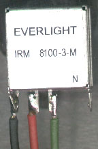
The leg of the IR detector closest to the tab on the case. Check the schematic
that comes with the detector to make sure that the one you get matches the one
in my diagram. This is a photo of the detector that I got from RS. The black
wire is ground, the red goes to the 5 volt regulator (pin 14 of the 594). The
green wire goes to pin 4 of the 594.
These things are connected together. You can check them with an ohm meter
before powering it up for the first time.
-
TL594, pins 2, 15, 14, 13 and one end of R5.
-
TL594, pins 8, 11, 12, positive end of C2, and one end of R1.
-
Striped end of D1, the other end of R1 and one terminal of the 3 amp fuse.
-
Pin 9 and one end of R2.
-
Pin 10 and one end of R3.
-
Pin 14 on the 594 is the 5 volt regulator output.
-
Pins 9 and 10 are the outputs for the LEDs. They go high when the chip is
triggered.
-
Pin 4 is being used for the input from the IR detector. The chip can be
controlled by other pins but this is the easiest way.
Even more (somewhat) useless information
-
Pins 5 and 6 are the timing pins for the 594. They determine the output
frequency for the output on pins 9 and 10. The repeater has to have a 40,000hz
output frequency for the IR receiver on the TV or VCR to be able to detect it.
-
You should use heat shrink tubing on the IR LED's leads to prevent a short
circuit.
-
You should make sure that the signal from the repeater and the signal from the
remote control can't be seen at the same time by the device that is being
controlled. If both signals reach the device at the same time you will be blown
to bits.... Well maybe not but the device won't work properly.
-
All of the IR detectors that I've bought from RS have an intermittant pulse
output with no input. This causes the indicator LED to blink at random
intervals. You may not want the indicator LED mounted where you can see it.
Especially if you drive very much after dark.
-
The leads on C2 should be as short as possible and the capacitor should be
mounted as close to the 594 as possible.
-
D1 is to protect the IC and detector if the repeater is connected with reverse
polarity.
Thermally controlled fan driver
Controlling a fan with a thermistor
If you only want the fans to come on at a specific temperature, you can use a
thermistor. Since you won't be designing a circuit for mass production, you
want something that is fairly flexible and can produce the desired results
without a lot of testing. The diagram below is a circuit which uses an op amp
as a comparator with an output which goes high when pin 5 goes higher than pin
6.
 When initially setting up this circuit you need to adjust the voltage at pin 6
to 1/2 of the voltage on pin 8. This will cause the fan to switch on at
approximately 150F. You can set it lower if you want the fan to come on earlier.
When initially setting up this circuit you need to adjust the voltage at pin 6
to 1/2 of the voltage on pin 8. This will cause the fan to switch on at
approximately 150F. You can set it lower if you want the fan to come on earlier.
If you want to use an FET to control the fan, the diagram below shows you how
to connect the FET to the op amp. Keep in mind that you must insulate the tab
of the FET. If the tab of the FET touches to ground, the fan will run.
If you need more info on the circuits above, E-mail me and I'll try to help.
Possible supplier: Mouser electronics http://www.mouser.com
Parts list:
Thermistor: 334-4227-503
Potentiometer: 531-PT10V-100k (not critical)
Op amp: 511-LM358N (critical)
FET: 570-IRF540
Bipolar transistor: 625-MPSA06 (or equal)
Resistors: None are critical and can
likely be purchased at Radio Shack.
EXCESS JUNK
Switching through the use of an NPN transistor:
The Diagram below shows the schematic diagram for the circuit which reduces the
current demand from the remote out of the radio. The relay would normally draw
approximately 0.170 amps of current. The transistor reduces the demand to less
than 0.005 amps of current. The transistor should be rated to handle at least
.4 amps and 20 volts. If the diode is ommited, the transistor must be able to
withstand 200 volts.
Possible supplier: Radio Shack
Parts list:
Bipolar transistor: 2N4401 RS # 276-2058
Resistors:  4700 ohms RS # 271-1330
You May Be Interested in My Other Sites
-
This site was started for pages/information that didn't fit well on my other sites. It includes topics from backing up computer files to small engine repair to 3D graphics software to basic information on diabetes.
-
This site introduces you to macro photography. Macro photography is nothing more than the photography of small objects. It can take quite a while to understand the limitations associated with this type of photography. Without help, people will struggle to get good images. Understanding what's possible and what's not possible makes the task much easier. If you need to photograph relatively small objects (6" in height/width down to a few thousandths of an inch), this site will help.
-
If you're interested in air rifles, this site will introduce you to the types of rifles available and many of the things you'll need to know to shoot accurately. It also touches on field target competition. There are links to some of the better sites and forums as well as a collection of interactive demos.
-
This site helps anyone new to computers and anyone with a basic understanding of computers with a desire to learn more about the internal components of a computer. If you have a computer that you'd like to upgrade but don't know where to start, this is a good site for you.
-
This site is for those who want to begin racing karts but don't fully understand how the various parts work. It's mostly interactive demos that show how the various parts of the kart work.
Bridging module
See the op amps page.
Try this for the transmitter receiver thing
Blown fuse indicator
This circuit will light the green led when the fuse is good and the red led
when the fuse is blown.
v.1
This circuit powers the green led directly from the B+ terminal. The red led is
kept off by Q1. When the base of Q1 is high (no, not stoned), the current is
shunted to ground through the transistor. When b+ falls to ground (when the
fuse blows), the transistor turns off and the current flows through the red LED. This circuit draws slightly more (but still a negligible amount) current than the next two circuits.
Probably the best form
 This design powers the green LED directly from the B+ terminal. The red LED is powered through Q2 when the the B+ falls to ground.
OR
third choice...
This may be a good choice if you want to monitor the remote output because it draws the least current from the monitored source. Of course, you would connect R5 to the remote terminal instead of the B+ terminal.
Q1 and Q2 are used as emitter followers. Q1 drives the green LED when the input
to R5 goes high (12 volts). Q2 drives the red led when the input to R5 goes low
(ground). Q3 is the enable/disable transistor which opens the ground path when
the remote output is low. This turns the leds off when the system is off.
If multiple circuits (inside dashed line) are used, I would recommend using the
optional TIP31. The tab of the TIP31 must be insulated.
Possible supplier: Radio Shack
Parts list:
Bipolar npn transistor: (Q1 & Q3) 2N4401 RS # 276-2058
Bipolar pnp transistor: (Q2) PN2907 RS # 276-2009
Bipolar npn transistor: (option for Q3) TIP31 RS # 276-2017
Resistors:
R1,R2,R3: 1000 ohms RS # 271-1321
R4: 47000 ohms RS # 271-1342
R5: 4700 ohms RS # 271-1330
R6,R7: 2200 ohms RS # 271-1325
Motor control with limit switches
 This controller will start a motor spinning in direction 'A' when the control voltage is applied to the 'control' terminal. It will run in direction 'A' until the control voltage is removed or limit switch #1 is connected to ground. When the control voltage is removed, the motor will spin in direction 'B' and will do so until limit switch #2 goes to ground or the control voltage goes high again.
Another explanation:
- Neither limit switch grounded:
Motor runs in one of two directions. The direction of ratation is determined by the control voltage. It will not stop running until one or both of the limit switches are connected to ground.
- Control high:
Motor runs in direction 'A' until limit switch #1 is connected to ground. The limit switch can actually be anything including a piece of wire with the insulation stripped off of the tip.
- Control low:
Motor runs in direction 'B' until the control goes high or the limit switch is connected to ground.
- Safety switch will act like a master switch to shut everything off if something goes haywire (technical term).
Possible supplier: Radio Shack
Parts list:
Bipolar npn transistor: (all transistors) 2N4401 RS # 276-2058
Resistors:
R1,R2,R3: 4700 ohms RS # 271-1330
R4: 47000 ohms RS # 271-1342
Relays: 4PDT  RS # 275-214
Relay socket: RS # 275-221
Safety switch: RS # 275-324 (not critical)
Diodes: 1N4003 RS # 276-1102
!2 volt car battery: RS # 275-just kidding
|

